- HOME
- Technical Information
- TORELINA™ PPS Resin
- Various Properties
- Mechanical Properties
- Weld Properties
Weld Properties
Ⅰ. What Are Welds?
 Fig. 5.76 Simple schematic diagram of welds
With injection molded products, fragile portions called "welds" are almost always formed near those portions in the mold where the molten resin flows meet, such as multipoint gate systems, metallic inserts, structural ribs, and openings. Near welds, V-shaped grooves called "weld lines" may be formed due to adhesion failure. These result in a poor appearance, as well as adversely affecting strength and toughness due to stress concentrations (resulting from the notch effect), and so on. Welds formed near an opening in an injection molded product are shown in the following simple schematic diagram. The molten resin branches into two flows at position (1), and then the two flows pass around the opening (position (2)), and meet at position (3). In this case, counterflow welds are formed near the opening where the molten resin flows meet each other head on, while parallel flow welds are formed a slight distance from the opening. (Fig. 5.76) Of these two types of weld, it is necessary to pay particularly close attention to counterflow welds, from the perspective of its mechanical properties. Near a counterflow weld, the orientation direction of the reinforcement differs from that of the reinforcement around the weld, as shown by the arrows, so the mechanical properties are adversely affected in the same way as described in Section 5.6, "Anisotropy." In addition, stress concentration is more likely to occur, possibly causing the mechanical properties to become poorer than those in the transverse direction. Thus, the mechanical properties at welds are compound properties that are affected by a range of factors such as adhesion failure, anisotropy, and stress concentration. When designing a product, therefore, sufficient attention must be paid to these welds.
Ⅱ. Weld Test
 Fig. 5.77 Weld test piece (ISO 20753 type A1)
To determine the weld strength, counterflow welds are formed in the middle of a product by filling a dumbbell shape test piece (type A1) conforming to the ISO standard (ISO 20753) with molten resin, symmetrically from both sides. (Fig. 5.77) The weld strength is influenced by the mold, including its gas vents, in addition to the material composition and the injection molding conditions. For details, check the molding condition dependence.
Table. 5.8 Weld properties of TORELINA™ (23℃)
| Item | Units | Glass fiber reinforced | Glass + filler reinforced | Elastomer improvement | ||||
|---|---|---|---|---|---|---|---|---|
| A504X90 | A604 | A310MX04 | A610MX03 | A673M | A575W20 | A495MA2B | ||
| Non-weld strength | MPa | 190 | 195 | 130 | 140 | 150 | 150 | 150 |
| Weld strength | 65 | 73 | 46 | 55 | 70 | 45 | 52 | |
- ※Test method: Conforms to ISO 527-1 and -2.
Ⅲ. Influence on Mechanical Properties
| Grade name | Tensile strength (MPa) |
Tensile elongation (%) |
Young's modulus (GPa) |
|
|---|---|---|---|---|
| A504X90 | Non-weld | 190 | 1.6 | 16.0 |
| Weld | 65 | 0.6 | 12.5 | |
| Retention rate(%) | 34 | 38 | 78 | |
The tensile strength and the tensile elongation of welds are half, or even less than, those of non-welds, and the elastic modulus is also lower. (Table. 5.9 and Fig. 5.78) In particular, decreases in the tensile strength are greater than those caused by anisotropy, and this is considered to be due to stress concentration, in addition to the anisotropy of the reinforcement at the welds. For unreinforced PPS grades such as A900, there are no decreases in the tensile strength (yield strength) at the welds because there is no anisotropy due to the reinforcement. If weld lines are formed, however, the tensile elongation may decrease due to the stress concentration. (Fig. 5.79)
 Fig. 5.78 S-S curve of a weld test piece (A504X90)
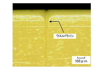 Fig. 5.79 Weld line (A670T05)
Ⅳ. Temperature Dependence
The temperature dependence of the weld strength of seven representative grades of TORELINA™ is shown in Figs. 5.80 to 5.82, and the weld strength retention rates are listed in Table. 5.10. In terms of weld strength, linear PPS types such as A604 and A610MX03 are superior to cross-linked PPS types such as A504X90. A673MB with a low reinforcement content is excellent in terms of weld strength.
 Fig. 5.80 Temperature dependence of welds (GF-reinforced PPS)
 Fig. 5.81 Temperature dependence of welds (high-filler PPS)
 Fig. 5.82 Temperature dependence of welds (elastomer improvement PPS)
| Grade name | Strength retention rate (%) |
|---|---|
| A504X90 | 34 |
| A604 | 38 |
| A310MX04 | 35 |
| A610MX03 | 39 |
| A575W20 | 29 |
| A673M | 46 |
| A495MA2B | 34 |