- HOME
- Technical Information
- TORELINA™ PPS Resin
- Various Properties
- Secondary Processing
- Miscellaneous (Screw Fastening and Self-Tapping)
Miscellaneous (Screw Fastening and Self-Tapping)
Ⅰ. Screw (Bolt) Fastening
To fix a resin molded product to a metallic main body and to join resins together, screw fastening methods such as the following can be used: Fastening through a prepared hole in a molded product with a nut and a bolt; tightening a screw into a female thread in the molded product; and self-tapping in which a self-tapping screw is driven into a resin boss having a prepared hole, without using a female thread. In general, resin is inferior to metal in terms of strength, creep properties (stress relaxation), and so on. Thus, cracking due to an excess tightening torque, thread fracture, and loosening may present problems.
1 Names of thread sections
The names of the sections of a thread are given in Fig. 10.35.
(a) Double-threaded right, parallel male thread
(b) Axial planes of parallel female thread and parallel male thread
Fig. 10.35 Names of thread sections
- ※Reference: New Edition, 9th Edition, A. Basic and B. Application, Mechanical Engineers' Handbook, compiled by the Japan Society of Mechanical Engineers
2 Stress that occurs during bolt tightening
 Fig. 10.36 Axial force during bolt tightening
When two molded products are fastened together using a nut and a bolt, as shown in Fig. 10.36, and a tension force F and a compression force F, which balance each other out, exist in the bolt shaft (no external force), this force F is called a prestressing force (or axial force), and indicates the initial tightening force.
If a bolt, which has male thread, and a nut, which has female thread, are to be tightened together with the torque method, the tightening torque T and the axial force F have the relationship given by Formula 10.1.
The first term of the right side of Formula 10.1 indicates the friction torque acting on the thread face, the second term
  indicates the torque acting on the bolt shaft, and the third term
  indicates the friction torque acting on the nut seating face. If tightening is performed with the torque method without using a lubricant, most (about 90% or greater) of the torque energy will be converted to heat due to the friction associated with the first and third terms. To increase the efficiency of the tightening torque, the friction coefficient must be reduced.

If Formula 10.1 is applied to general metric screws (α = 30°), Formula 10.2 is obtained.
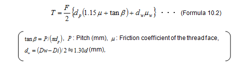
Assuming that  , the relationship between the tightening torque and axial force is as given in Fig. 10.37 for the metric screws given in Table 10.12, which have their respective nominal diameters (outside diameters). If the axial force is exceedingly high, radial cracks may occur, emanating from the tightening portion of the molded product. The cause of this is assumed to be as follows: Compression stress is acting on the molded product surface, but the bolt hole attempts to deform to expand laterally, like insert metal, so that a tension stress arises inside the molded product. If the axial force exceeds the permissible stress, cracks may result.
 Fig. 10.37 Torque in metric screws in relation to axial
| Screw nominal designation | M2 | M3 | M4 | M5 | M8 | M10 | M12 | M14 | M16 | |
|---|---|---|---|---|---|---|---|---|---|---|
| Nominal diameter d | mm | 2 | 3 | 4 | 5 | 8 | 10 | 12 | 14 | 16 |
| Pitch P | mm | 0.40 | 0.50 | 0.70 | 0.80 | 1.25 | 1.50 | 1.75 | 2.00 | 2.00 |
| Effective diameter dp | mm | 1.74 | 2.68 | 3.54 | 4.48 | 7.15 | 9.03 | 10.86 | 12.70 | 14.70 |
| Root diameter dr | mm | 1.57 | 2.46 | 3.24 | 4.13 | 6.65 | 8.38 | 10.11 | 11.84 | 13.84 |
The torque for loosening a nut is expressed by Formula 10.3, because the second term of the right side of Formula 10.1  , the torque acting on the bolt, acts in the negative direction. From Formula 10.3, the unwinding torque is about 80% of the tightening torque.

Ⅱ. Self-Tapping
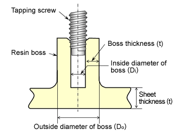 Fig. 10.38 Self-tapping
To fasten a resin part with a screw, the self-tapping method (Fig. 10.38) may be used, where a resin boss with a prepared hole is provided on a molded product and a self-tapping screw is driven into it for fastening.
1 Tapping screw
For the self-tapping of TORELINA™, tapping screws of any of types A to C can be used. Note, however, that if the pitch is 0.8 mm or less, the screw may scrape the prepared hole of the boss, failing to obtain a sufficient tightening force.
2 Designing a resin boss
It is necessary to design a resin boss in accordance with the shape of the tapping screw, so that the strength of the screw can be fully exploited.
(1) Prepared hole diameter and inlet shape
An appropriate diameter is equivalent to or slightly less than the effective diameter of the tapping screw being used, slightly greater than the root diameter, and about 85% of the nominal diameter of the screw. The percentage of the thread engagement, given by Formula 10.4, should be about 50% to 70%. If the prepared hole diameter is too large, the female thread of the resin boss may break during screw tightening, and if the prepared hole diameter is too small, the resin boss or the screw itself may break. The inlet of the prepared hole must be dish-shaped or curved, whenever possible, to provide an introducing hole (depth: Around 1 mm, diameter: Outside diameter of the screw + 0.1 to 0.2 mm), so that the portion around the inlet is not damaged during tightening.

(2) Outside diameter of the boss
The standard diameter is 2.5 times the nominal diameter of the screw. If the outside diameter of the boss is too small and the wall thickness is small, short shot, weld, and other molding failures may result. Even if such failures do not occur, lateral or longitudinal cracks may occur.
(3) Penetration depth
The standard depth is 2.5 times the nominal diameter of the screw. If the penetration depth is too small, the resin female thread may be broken.
(4) Sheet thickness
The thickness must be about the same as the nominal diameter of the screw. If the strength is insufficient, secure a sufficient corner radius (0.3 to 0.5) and take appropriate measures such as rib reinforcement. Note that, if the sheet thickness is too large, internal sink marks may occur.
3 Designing the outside diameter of the boss
While the boss is being tightened with a screw, stress occurs that will cause lateral and longitudinal cracks in the boss.
(1) Longitudinal cracks

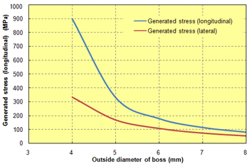 Fig. 10.39 Outside diameter of the boss in relation to the generated stress
For example, assuming that the nominal diameter of the screw is M3,  is 2.57 mm,
 is 7.5 mm, and the fracture strength of the M3 screw itself is 2450 N, the relationship between the generated stress and the outside diameter of the boss is determined. Table. 10.12 lists the pitches and effective diameters of the M3 screws to be used.(
 := 0.5 (mm),
  = 2.68 (mm))If the tightening torque is known, the axial force is determined from Formula 10.2 or Fig. 10.32, but in this case, assuming that the fracture strength of the screw is the maximum axial force F, and each is assigned to Formulas 10.5 and 10.6, Fig. 10.39 can be obtained. It can be seen that, for the generated stress to be 100 MPa or less, the outside diameter of the boss
  must be 7 mm or greater.
(2) Lateral cracks
Lateral cracks can be determined by using Formula 10.7.

The relationship between the outside diameter of the boss and the generated stress (lateral), as determined under the same conditions as those for longitudinal cracks, is shown in Fig. 10.39. It can be seen that, for the generated stress to be 100 MPa or less, the outside diameter of the boss must be 6 mm or greater.
4 Designing the prepared hole depth or the effective length of the screw
If the penetration depth is too small, the female thread of the boss breaks. The shear stress that is generated at the root of the female thread  can be determined from Formula 10.8.

 Fig. 10.40 Effective length of the screw in relation to the pull-out strength
For example, assuming that the nominal diameter of the screw is M3, κ is 0.82, is 65 MPa, the relationship between and the pull-out strength of the screw is as shown in Fig. 10.40. If the effective depth is 6 mm or greater, the pull-out strength exceeds the fracture strength of the screw itself, 2450 N. A type-C tapping screw is tapered for three to four crests at the lower end, and this tapered portion does not make a sufficiently contribution to the linkage. It is necessary to allow for this portion when estimating the prepared hole depth of the boss.
5 Designing the sheet thickness of a section on which to provide the boss
The sheet thickness of a section on which to provide the boss can be determined from Formula (10.9).

For example, assuming that the nominal diameter of the screw is M3,  is 2450 N (fracture strength of the screw),
  is 65 MPa, is 7.5 mm, and is 2.57 mm, then t is 2.45 mm. It can, therefore, be said that for a screw with a nominal diameter of M3, the sheet thickness of a section on which to provide a boss should preferably be at least 2.35 mm.
6 Test example 1
On 6-mm t square sheets of TORELINA™ A504X90 and A310MX03, a 4.5 mm diameter prepared hole was drilled, and an M6 tapping screw was tightened to a torque of 3.92 N・m. Then, heat cycle treatment (200℃ × 30 min ⇔ room temperature x 30 min × 10 cycles) was performed, and the loosening torque was measured. For both A504X90 and A310MX04, the loosening torque decreases to 0.98 N・m (torque retention rate: 25%). In the heat cycle treatment, a high temperature and room temperature are applied repeatedly, causing a linear expansion difference in the contact surface between the screw and the resin boss, thereby decreasing the loosening torque. If the treatment temperature is higher than the mold temperature during molding, the dimensions change due to the influence of subsequent crystallization. Annealing is effective, but because the linear expansion difference is dominant, the suppression effect of annealing will be minimal. For this reason, when a high retention rate is required for the loosening torque, it should be designed with a metallic insert.
7 Test example 2
If a 1.8 mm diameter prepared hole (percentage of thread engagement: 35%) is drilled in 3 mm t square sheets of TORELINA™ A504X90 and A310MX04, and an M2 tapping screw (d: 1.8 mm, dr: 1.46 mm) is tightened to a torque of 0.4 N・m, the female thread of the resin boss breaks. If the prepared hole diameter is set to 1.5 to 1.6 mm (percentage of thread engagement: 73% to 92%), and the tightening and loosening the screw is repeated, the friction torque becomes too large, breaking the cross recess of the screw head.
After an M2.5 (d: 2.48 mm, dr: 1.90 mm) tapping screw was tightened and loosened repeatedly ten times to a tightening torque of 0.5 N/m, with a prepared hole diameter of 2.1 mm (percentage of thread engagement: 66%), the loosening torque was measured. This was found to be 0.35 to 0.4 N/m (retention rate: 70% to 80%), and no thread or other breakage was observed.
Ⅲ. Press-Fitting
 Fig. 10.41 Press-fitting
In processes involving the assembly of resin molded products, metallic shafts and so on are often fixed by press-fitting (Fig. 10.41). Press-fitting involves fixing with the stepping force generated by a press-fitting allowance  (Formula 10.10) and the friction between the shaft and the molded product. The force necessary for press-fitting and the pull-out force should essentially be equal, but in reality, the pull-out force is lower because of the influence of stress relaxation.
1 Permissible stress
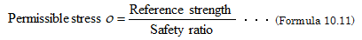
Designing a press-fitting allowance requires that the permissible stress  of the material be determined. The permissible stress is the reference strength divided by the safety ratio, as given by Formula 10.11. This is a critical stress established so that the material will not break within a certain period of time (preset service life). If the dominant factor leading to product breakage is the tensile strength, the reference strength is the tensile yield strength or the fracture strength, and if the fatigue properties are the dominant factor, the fatigue strength is the reference strength. The method for determining the safety ratio differs with the marginal conditions, such as the environmental conditions, product shape (including stress concentration and welds), and the importance (safety) of functions. It is assumed that, for metallic and other structural members, the safety ratio is 3 for static loads and 5 to 10 for dynamic loads. For thermoplastic resins, no clear guidelines have been established. It can be assumed that the safety ratio should be set to a value equivalent to or slightly higher than that of metal.
2 Designing the press-fitting allowance
If the press-fitting section is a boss, the press-fitting allowance can be determined by supplying the permissible stress σ to Formulas 10.12 and 10.13.

For example, the press-fitting allowance is determined for each of cylindrical molded products of TORELINA™ A504X90 (tensile fracture strength: 190 MPa, Young's modulus: 16,000 MPa, and Poisson's ratio: 0.36), A310MX04B (tensile fracture strength: 130 MPa, Young's modulus: 25,000 MPa, and Poisson's ratio: 0.34), A900 (tensile fracture strength: 80 MPa, Young's modulus: 4300 MPa, and Poisson's ratio: 0.40) (outside diameter : 20 mm) if a metallic shaft (outside diameter : 10 mm) is press-fitted into them. It is assumed that only a static load in the tensile direction is applied to the products, and the safety ratio is 3.
◆Example of calculating TORELINA™ press-fitting allowances
Permissible stress
From Formula 10.9,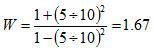
If it is assigned to Formula 10.10,
If it is assigned to Formula 10.8,
Inside diameter of A504X90:
Similarly, if the inside diameters of A310MX04 and A900 are determined
Inside diameter of A310MX04: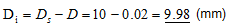
Inside diameter of A900:
allowance ratios for TORELINA™
| Grade | Critical press-fitting allowance ratio (%) |
|---|---|
| A504X90 | 0.72 |
| A310MX04 | 0.31 |
| A900 | 1.15 |
For grades that have a high reinforcement content and which have a high elastic modulus, the proportional limit below which the deformation during press-fitting can be followed is small, so the press-fitting allowance is also small. In addition, in actual press-fitting, the inside diameters of the press-fitting metal and the molded product fluctuate with the influence of the dimensional tolerance of the molded product, draft, and the linear expansion due to the working environmental temperature, so if the press-fitting allowance is small, production management will be difficult. As shown in Fig. 10.42, the influence of the outside diameter on the press-fitting allowance is small, whereas the strength and elastic modulus of the material have a large influence. Thus, the press-fitting allowance differs greatly depending on how the safety ratio is determined, as shown in Fig. 10.43. If the critical press-fitting allowance ratio of each grade of TORELINA™ is determined from Formula 10.14, which is a transformation of Formula 10.13, assuming a safety ratio of 1, Table. 10.13 can be obtained. Because of its high rigidity, PPS resin tends to have a lower critical press-fitting allowance ratio than other plastics. If the press-fitting allowance is made larger than the top end, boss breakage and buckling may occur. Thus, avoid making it excessively large.
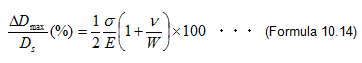
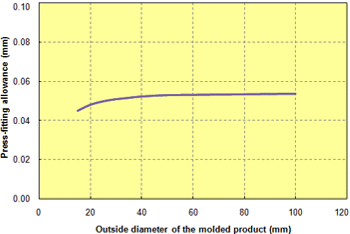 Fig. 10.42 Outside diameter of molded products in relation to the press-fitting allowance (A504X90)
 Fig. 10.43 Safety ratio in relation to press-fitting allowance (A504X90)
3 Hot press-fitting
Hot press-fitting is a variation whereby metal is heated to melt the resin on the molded product surface at the same time as press-fitting is being performed. This method is suitable if, for example, the critical press-fitting allowance ratio is small. Heating methods include heat press-fitting, where the shaft is directly heated, high-frequency press-fitting, where the shaft is heated by high-frequency waves, and ultrasonic press-fitting, where it is heated by the heat developed by the friction induced by ultrasonic waves. Knurling or grooving the metal to be inserted can prevent it from being removed. In this case, the molten resin enters the concave portions, so that a strong pull-out strength is obtained.