- HOME
- Technische Informationen
- AMILAN™ Nylon Resin
- Injection-molding
- Gate design
Gate design
Gate design should be considered during the product-design phase and before the mold-design phase.
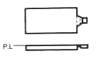
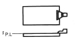
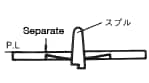
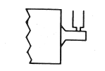
Locational relationships among the gate and other components
See Abbildung 4.1 for an illustration of the locational relationships among the sprue, gate, cavity and cold slug well.
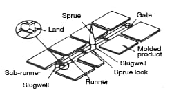
Abbildung 4.1: Locational relationships of
the gate and other components
Runner
The runner cross-section could take the shape of a circle, semi-circle or trapezoid; however, a circular shape is most common, as it has the lowest flow resistance. Table 4.1 shows the relationship between the product thickness and the diameter and length of a circular runner.
| Runner
diameter
(mmφ) |
Maximum runner length (mm) from the sprue bushing closest to the cavity | Product
thickness (mm) |
|---|---|---|
| 3-4.5 | 150 | 4.5 |
| 6-7.5 | 300 | 6 |
| 9 | 370 | 6 |
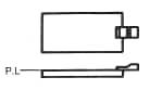
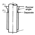
Abbildung 4.2 shows the relationship between depth h, widths W and B and radius r in a semi-circular and a trapezoidal runner.
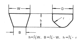
Abbildung 4.2: Semi-circular and trapezoidal
runner shapes
Types of gates
Table 4.2 sets forth 10 commonly used gate types. The red font indicates gates suitable for nylon applications.
Abbildung 4.3 illustrates different types of gate cross-sections.
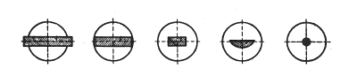
Abbildung 4.3: Different types of gate cross-sections
| Gate schematic | Gate type | Characteristics |
|---|---|---|
 |
Direct gate | Provided directly on the side or circumference of the molded product. Can be precisely machined, making it possible to control cavity fill rate and seal time relatively independently. |
 |
Fan gate | Suited for large, flat sheet-shaped molded products. Eliminates defects near the gate and minimizes strain. Also, makes it possible to fill the cavity with material quickly. |
 |
Straight top gate | Provided on the end or surface of the molded product. Suited for molded products where the side surface is important. Resolves jetting issues, but makes for tedious product finishing. |
 |
Fan top gate | Suited for large molded products where the side surface is important. |
 |
Ring gate | Provided on the outer circumference of the molded product. Material flows from the outer circumference into the center. Use of this type of gate may result in weld line issues and more difficult finishing. |
 |
Center diaphragm gate | Material flows from the center toward the outer circumference. Suited for concentric molded products. Makes for more difficult finishing. |
 |
Collar gate | Suited for cylindrical-shaped molded products. To adopt a collar gate, the mold must be made from three parts. Weld lines will not occur, but finishing is difficult. |
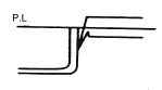 |
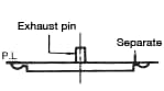
Submarine gate | The runner and molded product separate from each other during removal from the mold, eliminating the need for finishing. Can be used to mold microcrystalline nylons. Must take into account the gate locations and filling angle. |
 |
Pinpoint gate | No finishing work required. The mold must be made from three parts. Facilitates molding of microcrystalline nylon. |
 |
Tab gate | The first gate—located between the runner and tab—acts as a check valve that prevents the back-flow of molten material. The second gate facilitates the uniform filling of the cavity. However, using this type of gate makes for tedious finishing to avoid leaving residual stress in the molded product in the vicinity of the gate. |
Selecting the gate location
Ⅰ. Based on product performance
- Design: In terms of external appearance, where is it permissible to have gate marks and finishing marks?
- Dimensional accuracy: Inject from the center when molding parts that require circularity, such as gears and shafts. Do not locate gates in locations with stringent dimensional requirements.
- Strength: Predict where weld lines may occur and consider the strength of such sites. If strength cannot be compromised in such locations, change the gate location.
Ⅱ. Based on the number of products per shot
Consider whether each shot yields one or multiple parts.
Is the mold-opening pressure well-balanced in light of the runner, cavity placement and polymer-injection pressure? If mold-opening pressure is not properly distributed, burring and mold distortions could occur.
Ⅲ. Based on the economics of finishing work
Decide whether to use a pinpoint gate (which requires a mold made from three components), a submarine gate (which eliminates the need for finishing) or an ordinary gate.
Ⅳ. Based on the moldability of the material
Select the gate type and decide the gate location taking into account the material flowability, discoloration upon exposure to heat and molding strain.
Gate balance
Gate design should have the molten polymer arriving at all gates simultaneously and filling the cavity simultaneously. Poor gate balance can lead to flow marks, burn marks and other appearance issues, as well as strength disparities across molded products.
Ⅰ. Make the cavity layout balanced
Abbildungs 4.4 and 4.5 illustrate a design where the material flows uniformly across runners and arrives at all gates simultaneously. The drawback here is that the runners are relatively long.
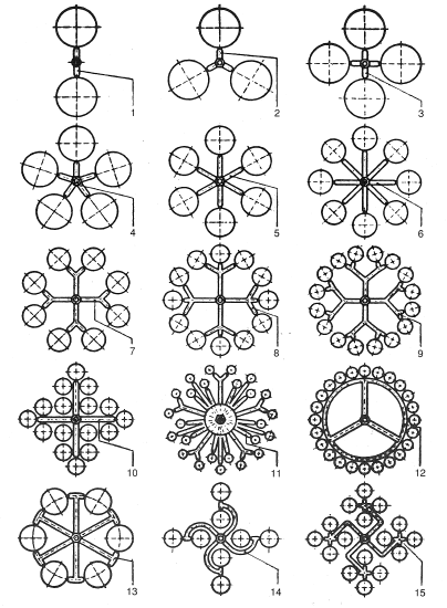
Abbildung 4.4: Gate balance
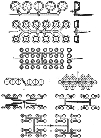
Abbildung 4.5: Gate balance
Ⅱ. Adjust the gate cross-section surface area
Assuming commonly used runners, try to achieve gate balance by adjusting the cross-section surface area of each gate to accomplish uniform filling.
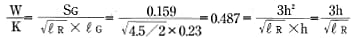
Formula 6:
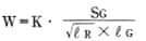
Whereas:
W: Weight of polymer passing through (g)
SG: Gate cross-section surface area(mm2)
![]() : Length of runner up to gate (mm)
: Length of runner up to gate (mm)
![]() :Length of gate land (mm)
:Length of gate land (mm)
K: A constant determined by the polymer properties and the mold
< Exercise >
Assuming you are using the runner illustrated below, calculate the cross-section surface area for each gate—SG1, SG2, SG3, SG4 and SG5
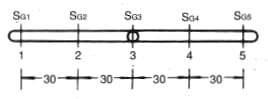
< Answer >
Assume the cross-section surface area of gate SG3which is in immediate contact with the sprue, is 1% that of the runner. In that case, SG3=0.01×π×4.52/4=0.159mm2. Assume the gate cross-section surface area shape is rectangular and that the relationship between gate width W and gate depth h can be expressed as W = 3h. In that case, SG3=W×h=3h2=0.159. Therefore, h2 = 0.053, h = 0.23 mm and W = 0.69 mm. So, gate land LG3would be 0.23 mm, the same as the gate depth.
Assuming:
![]() 1=
1=![]() 5=60,
5=60, ![]() 2=
2=![]() 4=30,
4=30, ![]() 3=4.5/2, SG=3h2,
3=4.5/2, SG=3h2, ![]() =h
=h
Based on formula 2.3:
Insert ![]() 1=
1=![]() 5=60and hi,5 = 1.25.
5=60and hi,5 = 1.25.
Insert![]() 2=
2=![]() 4=30 and h2h4=0.887
4=30 and h2h4=0.887
In conclusion,
SG1 and SG5 are 4.68mm2. SG2 are SG4 are 2.42mm2. SG3 is 0.159mm2, and W1 and W5 are 3.75 mm.W2 and W4are 2.7 mm, and W3 is 0.69 mm.
h1 and h5 are 1.25 mm. h2 and h4 are 0.887 mm, and h3 is 0.23 mm.
Gate dimensions
Use Table 4.3 as a guideline.
The safe and sure approach is to gradually widen the gates after molding and confirming the molded product outcome.
| Product thickness |
Circular Gate | Rectangular Gate | ||||
|---|---|---|---|---|---|---|
| Diameter (mm) |
Land length
(mm) |
Depth (mm) |
Width (mm) |
Land length (mm) |
||
| 3 mm or less |
nylon 6 |
1.0 to 1/2 of product thickness | No more than 1.0 | 1/2 of product thickness | Equal to product thickness (no less than 1.5) |
No more than 1.0No more than 1.0 |
| nylon 66 |
0.75 to 1/2 of product thickness | 0.75 to 1/2 of product thickness | - | - | - | |
| 3-6 mm | nylon 6 |
1.0-3.0 | No more than 1.5 | 1/2 of product thickness | 1/2 to 3/4 of product thickness |
No more than 1.5No more than 1.5 |
| nylon 66 |
0.75-3.0 | 0.75-3.0 | - | - | - | |
| 6 mm or more |
nylon 6 |
3.0-4.5 | No more than 1/2 of gate diameter | 3.0-4.5 | 4.5 | No more than 3.1No more than 3.1 |
| nylon 66 |
3.0-4.5 | 3.0-4.5 | - | - | - | |