- HOME
- Technical Information
- AMILAN™ Nylon Resin
- Injection-molding
- Injection-molding apparatus
Injection-molding apparatus
Injection-molding machine types and structures
Figure 2.1 illustrates three representative types of injection-molding machines.
The plunger type (a) uses an injection plunger to compress and transfer the material, which is heated and melted using a heating cylinder and a torpedo, then injected into the mold cavity.
The preplasticating type (b) comes with a separate heating and melting device for preplastication.
The inline screw type (c) uses a screw to compress and melt the material and is commonly used.
Different types of injection-molding machines share the following structural features.
- A pressurization mechanism for measuring a constant amount of material for each molding cycle
- A pressurization mechanism for advancing and injecting the material through the heating cylinder.
- A heating mechanism for heating and melting the material.
- A mechanism for opening, closing and holding the mold.
- A mechanism for controlling the injection-molding cycle.
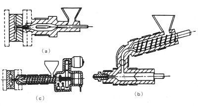
Figure 2.1: Representative types of injection-molding machines
Consider all three of the following points in selecting an injection-molding machine.
Ⅰ. Selecting the injection-molding machine
The molding machine must satisfy all three of the following equations.
Formula 1: Injection capacity:V≧(n×W+R)/(ρ/100)
Formula 2: Plasticization capacity: T≧(n×W+R)×1/1000×α
Formula 3: Clamping pressure: C>n×a×P×10.2
Whereas:
V: Injection capacity of the molding machine (cm3/shot)
T: Plasticization capacity of the molding machine (kg/h)
C: Clamping pressure of the molding machine (tons)
n: Number of molded products (quantity)
W: Weight of the molded product (g/piece)
R: Weight of the sprue and runner (g)
ρ: Density of material during melting (kg/m3)
i: Number of molding cycles per unit of time (shots/hr)
a: Projected areas of molded product (cm2)
P: Injection pressure (MPa)
Generally speaking, the plasticization capacity of an injection-molding machine is expressed in terms of the capacity to plasticize polystyrene at the molding machine’s maximum capacity. Formula 2 includes a correction coefficient α to account for the molding of nylon. A factor of 2 to 2.5 is expected to account for the difference in specific heat, melting heat and molding temperature between polystyrene and nylon. Using β as plasticization time as a proportion of total molding cycle time, you can project that:
α = 2.5/β
Ⅱ. Accounting for the size of the mold
Take into account factors such as the space between tie bars, location of mold installation holes, maximum mold open dimensions, minimum mold thickness, maximum mold dimensions, extruder-lever hole locations, nozzle hole sizes and radii and locator ring dimensions.
Ⅲ. Accounting for the molded product
To select the appropriate molding machine, take into account factors such as the space between tie bars, location of mold installation holes, maximum mold open dimensions, minimum mold thickness and whether production cycle times are short. When using a material containing a filler such as glass fibers, the material of the cylinder and screw should also be considered.
Nozzles
Although there is variance among nylon grades, generally speaking, nylon has relatively low viscosity and thus could easily leak from the nozzle. Nozzle leaks can result in non-uniformity in measured volumes and braking failures. To avoid nozzle leaks, use a closed nozzle such as those shown in Figure 2.2. A reverse-tapered nozzle such as that shown in Figure 2.3 can also produce favorable results when used with nylon.
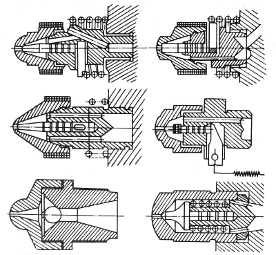
Figure 2.2: Closed nozzles for nylon applications
Figure 2.3: Injection-molding nozzle for nylon applications
Screws and screw heads
Ⅰ. Screws
A screw for nylon applications in an inline screw injection-molding machine requires the following features.
- A short compression type shape is recommended. As shown in Figure 2.4, the screw is divided into the following components: a supply section, a compression section and a measurement section. In particular, to be effective, the compression part should come immediately before the measurement part and be capable of compressing on a quarter- to a half-turn.
- A long screw (L/D ≥ 20) is recommended.
- A compression ratio of 3-4 is adequate.
- Given the potential for wear, select a material that is resistant to corrosion and wear, e.g., treated with a special lining, particularly when handling glass-fiber reinforced nylon.
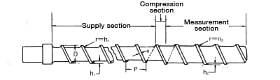
Figure 2.4: Screw for nylon applications
Ⅱ. Screw heads
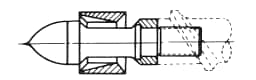
Figure 2.5
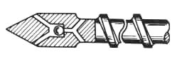
Figure 2.6
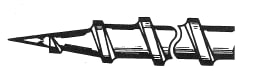
Figure 2.7
In an inline screw injection-molding machine, the screw also functions as a plunger, so selection of a screw head is important.
Compared to other resins, nylon has relatively low viscosity. During injection, back-flow of molten polymer could occur, so a screw head with a back-flow check valve such as that in Figure 2.5 or 2.6 is needed.
The screw head shown in Figure 2.7 would be appropriate for the injection-molding of a pyrolytic resin with a high viscosity, such as polyvinyl chloride.