- HOME
- Technical Information
- AMILAN™ Nylon Resin
- Injection-molding
- Mold
Mold
Mold structures and component names
Stripper plate type
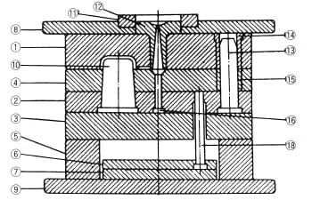
Ejector pin type
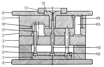
Figure 3.1: Molds for injection-molding applications
- Stationary side mold plate (JISB5106)
- Moving side mold plate (JISB5106)
- Support plate (JISB5106)
- Stripper plate (JISB5106)
- Spacer block
- Top ejector plate
- Bottom ejector plate
- Stationary side attachment plate
- Moving side attachment plate
- Core
- Locating ring (JISIB5111)
- Sprue bushing (JISB5112)
- Guide pin (JISB5107)
- Guide pin bushing (JISB5110)
- Guide pin bushing (JISB5110)
- Sprue lock pin
- Ejector pin (JISB5108)
- Return pin (JISB5109)
Importance of mold temperature controls
To improve molded product performance and enhance molding efficiency, control mold temperature properly with means such as a mold temperature modulator or a cartridge heater.
Nylon is a crystalline polymer; mold temperature is the greatest single factor influencing crystallinity.
Ⅰ. Functional properties
Table 3.1 shows the change in mechanical properties as a function of mold temperature. To obtain a molded product with high rigidity and great tensile and flexural strength, control to a high mold temperature to raise crystallinity. The tradeoff is that the product could become brittle. Use a lower mold temperature where different properties are required.
Ⅱ. External appearance of the molded product
Keep mold temperature low to increase transparency. To enhance surface glossiness, keep mold temperature no higher than 30C or no lower than 80°C. A mat-like surface is a molding defect caused by countless minute concavo convexities formed on the molded product surface and can arise even when the mold surface has been polished clean. Resolve mat-like surface problems by keeping mold temperature no higher than 30°C or no lower than 80°C.
| Properties | Unit | Mold temperature(°C) | Nylon | ||
|---|---|---|---|---|---|
| 6 | 66 | 610 | |||
| Tensile yield strength | MPa | 20 80 |
75-80 85 |
750 80 |
50 55 |
| Tensile breakdown elongation | % | 20 80 |
>200 150 |
150 100 |
>200 >200 |
| Flexural strength | MPa | 20 80 |
95 120 |
100 115 |
72 95 |
| Flexural modulus | GPa | 20 80 |
2.8 3.0 |
2.7 2.7 |
1.8 2.0 |
Ⅲ. Mold shrinkage and density
Figure 3.2: Change in mold shrinkage as
a function of mold temperature
Figure 3.2 shows an example of how mold shrinkage is influenced by mold temperature. Mold temperature is the single greatest molding condition affecting mold shrinkage. Therefore, first decide the mold temperature to be used before estimating mold cavity dimensions.
Figure 3.3 shows the change in density as a function of mold temperature. Density changes proportionally to crystallinity and should remain stable at a low density when using a mold temperature below 40°C and stable at a high density when using a mold temperature below 80°C. To avoid molded product quality issues, it is preferable to avoid using a mold temperature between 50-70°C, which constitutes a transitional range where a slight change in mold temperature can result in a substantial difference in crystallization temperature.
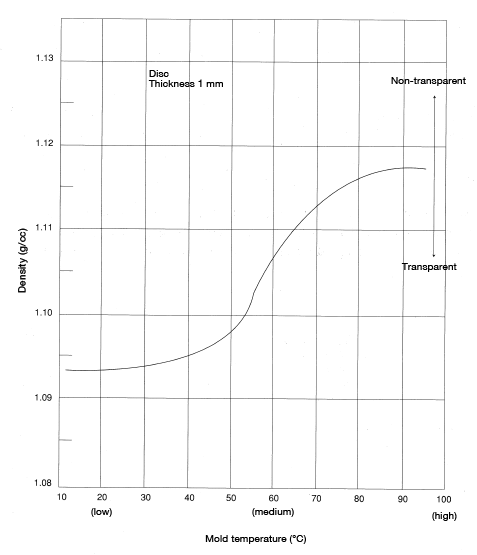
Figure 3.3: Mold temperature and density immediately following molding
Ⅳ. Moldability
A higher mold temperature results in more favorable molten polymer flowability (more details to follow). The molding cycle can be shortened by either lowering the mold temperature to accelerate solidification or by raising the mold temperature to facilitate filling with the molten polymer. To decide which approach to adopt, consider the shape and thickness of the molded product and the structure of the mold.
Ⅴ. Variance in mold temperature during molding
The mold absorbs heat from the molten polymer and releases heat into the coolant and mold surface. In a sense, the mold acts as a heat exchanger.
That said, there does exist a stable mold temperature suitable for a continuous molding operation-a temperature that accounts for the net effect of the heat absorbed from the molten polymer and the heat released into the coolant. Even in temperature-regulated molds, it takes some time to reach a stable temperature after molding begins. In molds without temperature regulation, it takes even more time to reach stable temperature, and all molding shots obtained before reaching that temperature must be discarded as defects. Until stable temperature is reached, molded product dimensions are not constant and the desired favorable properties cannot be obtained. Mold temperature control is needed to eliminate this waste.
A gas burner or torch burner may often be used to preheat isolated parts of a mold, but these techniques are not preferred as they result in heat strain.
Ⅵ. Preventing cooling strain
Non-uniform cooling across the different parts of a molded product may result in strain from non-uniform shrinkage, so it is important to design the mold so that every part of the molded product cools uniformly. Of course, it is impossible to completely eliminate strain caused by molecular orientation and molding pressure, but cooling strain can be eliminated through the appropriate control of mold temperature.
In designing a mold, the location of components such as the slide core, ejector pin, core insert and, in some cases, a beryllium copper cast cavity block may restrict the placement of coolant channels aimed at achieving the ideal uniform cooling within the mold cavity. In such cases, a warm (heated) coolant can be used on portions that cool more quickly to slow down the cooling process in those locations and achieve a uniform cooling (shrinkage) speed overall. Using heating in isolated locations has the added benefit of improving molten polymer flow within the cavity and enhancing moldability.
Designing mold temperature controls
Ⅰ. Design principles
As a principle of design, coolant channels take priority over ejector pins. Generally speaking, mold cavities have complex shapes. Many designers position the ejector pins first, then provide coolant channels as the mold structure permits. By then, trying to compensate using coolant flow and temperature settings becomes an uphill battle. Instead, it is important to start the mold design from the perspective of mold temperature control, first and foremost.
Ⅱ. Mold heat transfer surface area
The following formulas express the heat transfer surface area of mold coolant channels required to control mold temperature (negating any heat transfer that may take place by way of mold plates, nozzle contact or heat release into the atmosphere).
Formula 4:
Formula 5:
Whereas:
A: Heat transfer surface area(m2)
W: Molded product weight (kg)
N: Number of shots per unit of time (1/h)
Cp: Resin specific heat (1.4~2.1) (J/g·°C)
C: Coolant specific heat(4.2)(J/g·°C)
t1: Resin temperature(°C)
t0: Molded product removal temperature(°C)
ΔT: Average temperature difference between the mold and coolant(°C)
h: Laminar film heat transfer coefficient on the coolant channel side (90~140) (W/m2·°C)
λ: Coolant coefficient of thermal conductivity (600~700) (W/m·°C)
d: Channel diameter (m)
u: Coolant flow rate(m/s)
ρ Coolant density(1000)(kg/m3)
μ: Coolant viscosity(0.001)(Pa·S)
Figure 3.4 shows a monograph obtained by making some assumptions for the above values. Consider the heat transfer surface area obtained using the above formulas to be a minimum required value.
< Exercise 1 >
Estimate the required heat transfer surface area of coolant channels of a mold when performing molding under the following conditions: 70 g weight per shot, 60 shots per hour.
< Answer >
On the monograph provided in Figure 3.4, connect the points W = 70 g and N = 60 shots/hr. The point where that line intersects line A (A = 400cm2) is the required heat transfer surface area.
< Exercise 2 >
Assuming a mold coolant channel diameter of 12.7φ, estimate the length of the coolant channels in the above problem. If the size of the mold is 30 cm on each side, how many straight holes are needed?
< Answer >
The coolant channels need to be at least 100 cm long.
In a mold where each side is 30 cm, at least 3.3 holes—that is to say, 4 holes are needed.
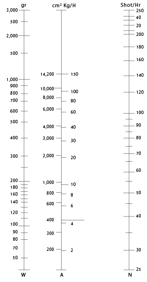
Figure 3.4: Required heat transfer surface area in a mold
Ⅲ. Size and distribution of coolant channels
In theory, the cooling distribution resembles the enthalpy distribution—or weight distribution—introduced to a cavity by the molten polymer.
To test whether the cooling distribution is appropriate, check the molded product hardness after molding using a cooling time that is shorter than the required time.
A coolant channel diameter of 9.5-12.7mmφ is appropriate. Coolant channels should be located 25-40 mm from the cavity surface. Too close and cooling will be non-uniform, resulting in cooling strain. Too far and cooling takes more time.
Preferably, coolant should flow from the part of the cavity furthest from the runners to the part of the cavity closest to the runners. In other words, coolant preferably flows in a direction opposite that of the molten polymer.
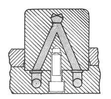 Figure 3.5: Cooling of a square core (1)
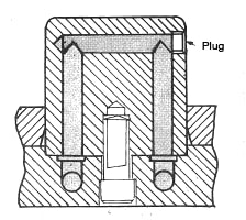 Figure 3.6: Cooling of a square core (2)
 Figure 3.7: Flow type coolant channels
 Figure 3.8: Coolant channels with an end dam
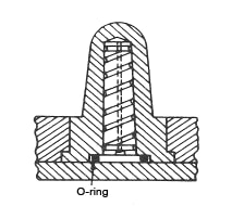 Figure 3.9: Cooling a wide round core
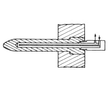 Figure 3.10: Cooling a narrow core (jet stream type)
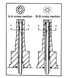 Figure 3.11: Ribbed coolant channels
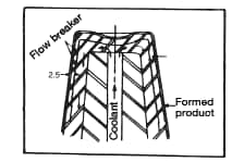 Figure 3.12: Core provided with a flow breaker
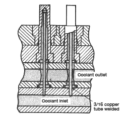 Figure 3.13: Core cooled using parallel channels
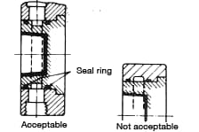 Figure 3.14: Cooling methods for the cavity side
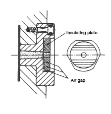 Figure 3.15: Sprue bushing provided with an insulating plate
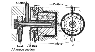 Figure 3.16: Mold cooling using a valve ejector
 Figure 3.17: Cooling of a sprue bushing
Gas venting
Air trapped inside the mold as a result of the inflow of resin material could cause molding defects. Such defects are particularly likely when injection speed is increased or a more precise mold is used. To improve molding results, vent gas to the extent no burring—or at least only easily repairable burring—occurs.
Figures 3.18 through 3.21 show gas venting methods.
Molding defects resulting from improper gas venting include scorching caused by diesel combustion (combustion of compressed gas under high temperature and high pressure), welding adhesion defects, and air bubbles caused by trapped air.
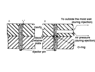 Figure 3.18: Gas venting using ejector pins
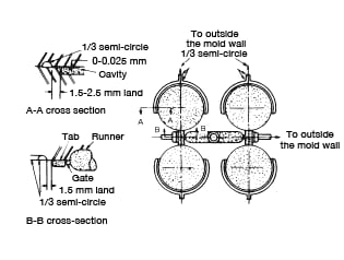 Figure 3.19: 4-cavity continuous gas vent
 Figure 3.20: Mold with continuous gas venting
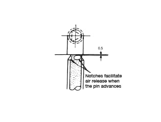 Figure 3.21: Gas venting using an ejector pin
Draft angle
The draft angle varies based on factors such as the complexity of the molded product shape, cavity depth and product thickness. Ordinarily a draft angle of at least1/2to 1° is needed.
Molded product ejection methods
Locate ejector pins to facilitate molded product ejection from the mold. The location of ejector pins should be distributed well to avoid causing deformation or strain in the molded product during ejection from the mold. Locate the ejector pins where any marks on the molded product will be hidden and thoroughly polish pin tips. See Figure 3.22 for sprue ejector pin shapes.
Figure 3.23 illustrates the use of ejector pins to eject a molded product. Figure 3.24 illustrates the use of a stripper plate, and Figure 3.25 shows the use of a sleeve. Select the method most suited to the molded product shape.
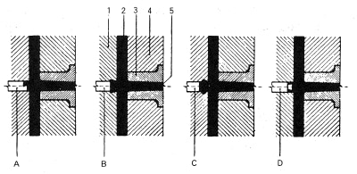
Figure 3.22: Sprue ejector pin and its removal
A: Z-type B: Reverse taper C: Groove D: Circular cone
1.Moving plate 2. Runner 3. Sprue bushing 4. Stationary plate 5. Sprue hole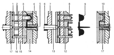
Figure 3.23: Ejector pin
1. Ejector plate (upper), 2. Ejector pin 3. Moving plate
4. Plate mounted on stationary mold 5. Sprue 6. Spring
7. Plate mounted on moving side 8. Core 9. Molded product
10. Core insert 11. Sprue bushing 12. Sprue ejector pin 13. Ejector frame
14. Stationary plate 15. Catch plate 16. Return pin 17. Ejector plate (lower)
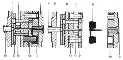
Figure 3.24: Ejector stripper plate
1. Ejector plate (lower) 2. Retaining bolt 3. Plate mounted on stationary mold 4. Spring
5. Plate mounting on moving mold 6. Catch plate 7. Guide pin 8. Molded product
9. Sprue bushing 10. Stationary mold plate 11. Stripper plate 12. Return pin
13. Moving plate 14. Core insert 15. Core 16. Sprue ejector pin
17. Ejector plate 18. Ejector bolt
Figure 3.25: Ejector sleeve
1. Ejector sleeve 2. Core insert 3. Moving mold mounting plate
4. Moving side fixing plate 5. Core 6. Moving plate
7. Molded product 8. Stationary plate 9. Sprue
10. Return pin 11. Advancing moving mold plate 12. Cooling pipe
13. Core insert 14. Ejector plate (upper) 15. Ejector plate (lower)