- HOME
- Technical Information
- AMILAN™ Nylon Resin
- Injection-molding
- Estimating molding cycle time
Estimating molding cycle time
Molding cycle time
The following formula expresses the total cycle time t for injection-molding.
Formula 19: t = td + ti + tc
Whereas:
td: intermediate time
The sum of the time required to open and close the mold (referred to as the dry cycle in injection-molding), to remove the molded product from the mold, to place inserts in the mold and to apply parting agent.
ti: injection time
The sum of the time required to fill the mold cavity with molten polymer and to replenish the mold with material to avoid voids and sink marks.
tc: cooling time
The time required to coagulate the molten polymer in the cavity and to cool to a temperature and solidify within the mold so that the ejector pins will not cause deformation or strain in the molded product during part release.
Intermediate time
Recent improvements and advances in injection-molding equipment have led to the emergence of machines featuring very short dry cycle times. However, the shorter the dry cycle time, the more thought that needs to go into the material and design of the mold. The impact load increases, so the mold structure must be solid. Also, the molded product should release automatically. With shorter dry cycle times, it is important to use inserts as minimally as possible. In any event, the intermediate time can be accurately forecast based on the molding machine, product and molding materials.
Injection time
Obtain a rough estimate of the polymer filling time using the cavity volume (cm3) and the injection rate (cm3/sec). Next, depending on the thickness and complexity of the molded product and requirements for dimensional precision, add on time for dwelling to calculate the injection time.
Note that the injection rate of a molding machine is influenced by injection speed controls, cavity wall thickness and shape, gate cross section surface area, material grade, molding conditions (polymer temperature, mold temperature, injection pressure) and more.
While these factors influence injection rate, the injection rate is usually 15-25cm3/sec per ounce in a standard inline screw injection-molding machine. Measure the injection rate after beginning molding, and gather data to assist future estimation efforts.
Cooling time
To estimate the cooling time of an ordinary molded product, use an equation related to the one-dimensional heat in a plane-parallel plate.
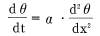
Based on the above equation, the relationship between cooling time tc(sec) and the central temperature of the plate at that time θ(°C) can be expressed in as follows.
Formula 20:
Whereas:
ℓ: the maximum thickness (m) of the molded product
α: temperature conductivity rate (m2/S) of the polymer
θ: Temperature (°C) of the polymer in its center at tc.
See Table 6.1.
Decide the temperature at which the part can be ejected using the ejector pins, based on the shape of the molded product and the location of the ejector pins, and make that temperature tc.
(Generally, θ is used as the load deflection temperature under a low load (0.45 MPa).
θs: Mold temperature (°C)
θ0: Initial temperature (°C) of the polymer
| Type | Nylon 6 | Nylon 66 | |
|---|---|---|---|
| Name of grade | CM1017 | CM3001-N | |
| α : FTemperature conductivity rate(mm2/sec) | 0.075 | 0.060 | |
| θ : | Coagulation temperature°C | 195 | 240 |
| Cooling temperature (°C) at center of part | 185 | 182 | |
For your reference, Table 6.2 shows the temperature conductivity rates and cooling temperatures for other thermoplastic resins.
Performing calculations using formula 20 provided above can be tedious. For convenience’s sake, use Figure 6.1. For molded products having a thickness greater than 3 mm, use the time required for a spot within the product located an arbitrary distance from its surface to reach θ°C as the cooling time. Doing so will provide a practical means of finding an appropriate cooling time without risking deformation upon ejection of the product from the mold. See Figure 6.2 for a graph expressing the ratio of cooling time using the center of the part to cooling time using an arbitrary distance x from the part surface.
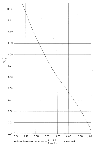
Figure 6.1: Estimating cooling time
| Material | α (mm2/sec) | θ (°C) |
|---|---|---|
| Polystyrene | 0.077 | 87 |
| ABS resin | 0.075 | 98 |
| AS resin | 0.075 | 98 |
| Polymethacrylate | 0.065 | 90 |
| Polyvinyl chloride | 0.068 | 60 |
| High density polyethylene | 0.102 | 76 |
| Polycarbonate | 0.098 | 148 |
Figure 6.2: Coagulation of planar plates
< Exercise 1 >
Estimate the cycle time when simultaneously molding four CM1017 60φmm discs having a thickness of 3 mm using a three-ounce screw type injection-molding machine. Molding conditions: polymer temperature 250°C, mold temperature 65°C.
< Answer >: t = 18 seconds, arrived at by referencing Figure 6.1 and Table 6.1.
< Exercise 2 >
Using the same molding equipment as in Problem 1, estimate the cycle time required to make the same product using a CM3001-N material. Molding conditions: polymer temperature 280°C, mold temperature 70°C.
< Answer >: t = 23 seconds, arrived at by referencing the above problem and Figure 6.1.
< Exercise 3 >
Estimate the cooling time for a 60 mmφ disc having a thickness of 6 mm. Because the thickness is greater than 3 mm, use as a cooling time the time required for a point 1.5 mm from the product surface to reach β. Also, calculate the temperature at the center of the product. The material is CM1017. Molding conditions are: polymer temperature 250°C, mold temperature 70°C.
< Answer >: tc = 13.4 seconds, arrived at by referencing Figures 6.1 and 6.2.
The temperature at the center at that time would be 237°C; 33.6 seconds would be required for the center to reach 185°C.