- HOME
- Technical Information
- AMILAN™ Nylon Resin
- Injection-molding
- Molding conditions
Molding conditions
The following descriptions speak to the feasibility of using nylon to form a product (flowability and fill characteristics) and what molding conditions are most appropriate when working from a product drawing.
Polymer flowability
Polymer flowability is affected by the cavity shape (molded product thickness and shape complexity, as well as flow resistance), grade, molding machine performance (maximum injection pressure, injection rate, mold clamp pressure), molding conditions (polymer temperature, injection pressure) and gate cross section surface area.
Figure 7.1 shows the results from a ribbon-shaped (5 mm width, 1-3 mm depth) spiral flow test. Please consider the above factors in interpreting the results.
The flow ratio is the value arrived at by dividing the greatest possible distance that can be reached by the polymer flowing into the cavity from the gate by the product thickness. Injection pressure represents net plunger pressure. The flow ratio becomes smaller with greater product thicknesses.
To apply the flow ratio to general molded products, use a correction coefficient of 0.55 to 0.75 in light of the above-mentioned factors.
< Exercise 1 >
Estimate the smallest moldable thickness of a 200 mmφ disc. Assume a material of CM1017 and the use of direct gates that fill from the center.
< Answer >
Based on Figure 7.1, 1/t = 162 (assuming a material of CM1017, an injection pressure of 70 MPa and a polymer temperature of 245°C). Using a correction coefficient of 0.7, 162 × 0.7 = 113. Because the gates fill from the center, 1 = 200/2 = 100 mm. Thus, 100/113 ≈ 0.9 mm. So the smallest possible thickness is 0.9 mm.
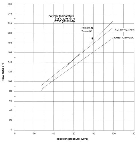
Figure 7.1: Nylon flow ratio
Melt viscosity
Melt viscosity can be used to compare the flowability of polymers. To calculate melt viscosity, discharge molten polymer at different temperature levels at a constant load with a constant nozzle using a Koka flow tester (a constant-load orifice-type flow tester). Calculate the melt viscosity based on the amount of molten polymer discharged.
Formula 21: μ=πR4P/8LQ
Whereas:
μ: Melt viscosity (Pa・S)
R: Nozzle radius(5×10⁻⁵)(m)
P: Pressure (2)(MPa)
L: Nozzle length(1×10⁻⁴)(m)
Q: Discharge velocity(m3/s)
Figure 7.2 shows the melt viscosity of each nylon grade. From the graph, refer to the molding condition settings for each grade. Generally, 100-300Pa・S is reasonable for injection-molding applications. That is supported in particular by the fact that nylon has far greater flowability than other thermoplastic resins.
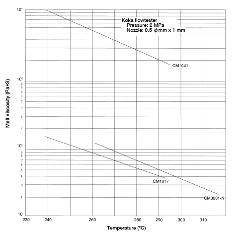
Figure 7.2: Change in melt viscosity of Toray nylon grades as a function of temperature