- HOME
- Technical Information
- TORELINA™ PPS Resin
- Various Properties
- Mechanical Properties
- Anisotropy
Anisotropy
Ⅰ. What Is Anisotropy?
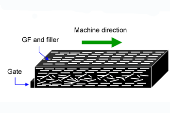 Fig. 5.56 Orientation of glass fiber (schematic diagram)
One of the great differences between PPS molded products reinforced with glass fiber/mineral filler and metallic products is the anisotropy in the mechanical and other properties. In general, the mechanical strength of an injection molded product is high in the direction in which the molten resin flows in the mold (MD), but is low in the transverse direction to the direction (TD). This occurs mainly because, as shown in the schematic diagram in Fig. 5.56, a high proportion of reinforcement with a large aspect ratio, such as glass fiber, is oriented in the machine direction due to the shear force that arises during injection molding. This orientation of the reinforcement varies due to factors such as the shape of the molded product and the mold, in addition to the injection molding conditions. The mechanical properties in the machine direction are the upper limits of the material, and the properties in the transverse direction can be considered as approximating to the lower limits (with the exception of welds). If, therefore, the maximum load acting in the transverse direction is about equal to or greater than about half the static strength in the machine direction, it is necessary to consider anisotropy when designing a product. Examples include the optimization of gates (shape and number), product wall thickness, and structural reinforcement (such as ribs).
Anisotropy evaluation uses a test piece made by cutting out the central part of a flat injection-molded plate and then polishing the surface of that part. All other test conditions conform to ISO178. (Fig. 5.57)
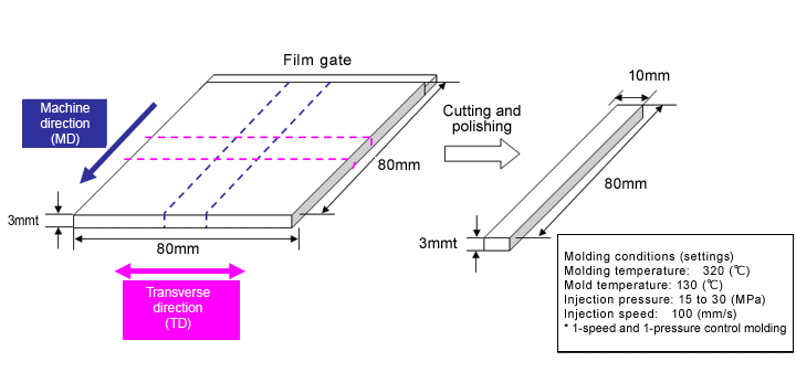
Fig. 5.57 Molded product for anisotropy evaluation
Ⅱ. Anisotropy in Flexural Strength
(Temperature Dependence)
| Grade name | Anisotropy (TD/MD) | |
|---|---|---|
| Flexural strength | Flexural modulus | |
| A504X90 | 0.5 | 0.6 |
| A604 | 0.5 | 0.6 |
| A310MX04 | 0.4 | 0.7 |
| A610MX03 | 0.5 | 0.7 |
| A575W20 | 0.5 | 0.6 |
| A673M | 0.6 | 0.5 |
The anisotropy in the flexural properties of six representative grades of TORELINA™ is shown in Figs. 5.58 to 5.69. If the anisotropy at 23℃ is expressed by a ratio in the transverse direction to the machine direction (TD/MD), this is as listed in Table. 5.6. An anisotropy of 1 indicates the absence of anisotropy. The closer the value is to zero, the larger the anisotropy. About half the flexural strength in the machine direction is equal to the flexural strength in the transverse direction. The following tendency arises: The lower the reinforcement content, the smaller the anisotropy, while the higher the reinforcement content, the larger the anisotropy. For the flexural modulus, the elastic modulus of the reinforcement itself is dominant, so high-filler PPS grades with high mineral filler and reinforcement contents, such as A310MX03 and A610MX03, tend to have a small anisotropy.
[General reinforced grades]
1 A504X90 (standard)
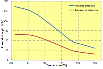 Fig. 5.58 Anisotropy in flexural strength (A504X90)
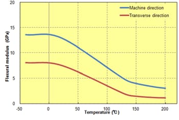 Fig. 5.59 Anisotropy in flexural modulus (A504X90)
2 A604
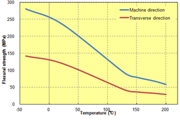 Fig. 5.60 Anisotropy in flexural strength (A604)
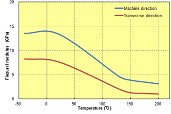 Fig. 5.61 Anisotropy in flexural modulus (A604)
3 A310MX04 (standard)
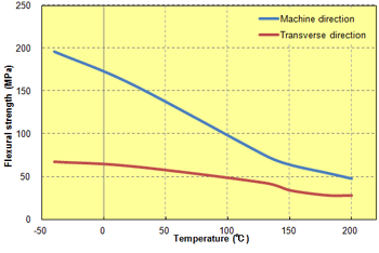 Fig. 5.62 Anisotropy in flexural strength (A310MX04)
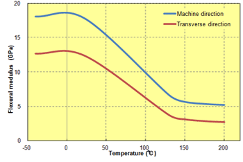 Fig. 5.63 Anisotropy in flexural modulus (A310MX04)
4 A610MX03
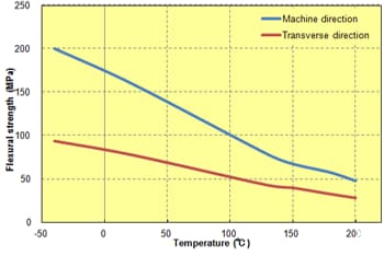 Fig. 5.64 Anisotropy in flexural strength (A610MX03)
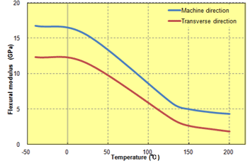 Fig. 5.65 Anisotropy in flexural modulus (A610MX03)
[Elastomer improvement grades]
5 A673M
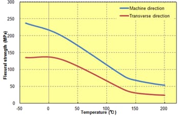 Fig. 5.66 Anisotropy in flexural strength (A673M)
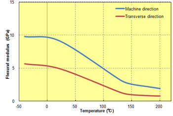 Fig. 5.67 Anisotropy in flexural modulus (A673M)
6 A575W20
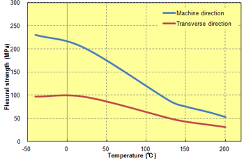 Fig. 5.68 Anisotropy in flexural strength (A575W20)
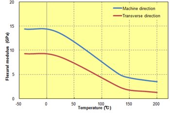 Fig. 5.69 Anisotropy in flexural modulus (A575W20)
Ⅲ. Anisotropy in Impact Strength (Temperature Dependence)
| Grade name | Anisotropy (TD/MD) |
|---|---|
| Notched Charpy impact strength | |
| A504X90 | 0.8 |
| A604 | 0.8 |
| A310MX04 | 0.8 |
| A610MX03 | 0.9 |
| A575W20 | 0.7 |
| A673M | 0.7 |
The anisotropy in the notched impact strength of six representative grades of TORELINA™ is shown in Figs. 5.70 to 5.75. The anisotropy at 23℃ is expressed by a ratio in the transverse direction to the machine direction (TD/MD), as in the case for the flexural properties. This is listed in Table. 5.7. The anisotropy in the impact properties is such that 70% to 80% of the impact properties in the machine direction is equal to the impact properties in the transverse direction. A310MX04 and A610MX03, which are reinforced with mineral filler with a small aspect ratio, tend to have a small anisotropy, whereas A575W20 and A673 of the elastomer improvement type tend to have a large anisotropy.
[General reinforced grades]
1 A504X90 and A604
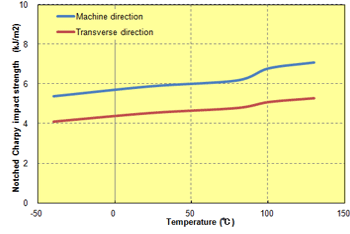 Fig. 5.70 Anisotropy in notched impact strength (A504X90)
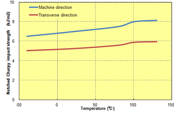 Fig. 5.71 Anisotropy in notched impact strength (A604)
2 A310MX04 (standard) and A610MX03
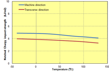 Fig. 5.72 Anisotropy in notched impact strength (A310MX04)
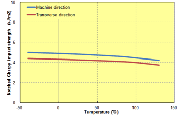 Fig. 5.73 Anisotropy in notched impact strength (A610MX03)
[Elastomer improvement grades]
3 A673M and A575W20
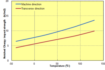 Fig. 5.74 Anisotropy in notched impact strength (A673M)
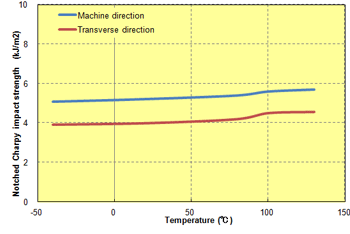 Fig. 5.75 Anisotropy in notched impact strength (A575W20)