- HOME
- Technical Information
- TORELINA™ PPS Resin
- Various Properties
- Thermal Properties
- Melt Viscosity Properties
Melt Viscosity Properties
A thermoplastic resin is in the solid state at temperatures less than the melting point, and
when it is heated above the melting point, it melts and thus exhibits fluidity. The degree of stickiness of
a liquid is expressed as its viscosity. Likewise, there are several methods of expressing the viscosity of a
thermoplastic resin (fluidity) when it melts. Representative methods include melt mass-flow rate (MFR), melt
volume-flow rate (MVR), a method using a measuring instrument such as a capillary rheometer, and bar flow
evaluation using an actual injection molding machine.
In general, the melt viscosity properties tend to depend on the molecular weight of the PPS polymer. For
reinforced grades and elastomer improvement grades, however, the fluidity is not necessarily correlated to
the molecular weight because of the influence of the reinforcement content and other factors.
Ⅰ. Melt Mass-Flow Rate (MFR)
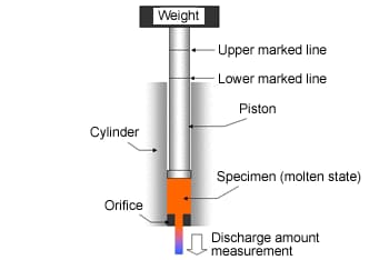 Fig. 6.9 Melt mass-flow rate
The MFR is a fluidity index, obtained by applying a constant weight to a specimen melted in a heating
cylinder to extrude it through an orifice (from one marked line to another) and converting the discharge
amount into a weight per ten minutes (units: g/10minutes). (Fig. 6.9) With the same cylinder temperature
and loading conditions, the higher the MFR value, the better the fluidity.
Usually, however, PPS is a non-Newtonian fluid that varies with the shear rate (or time), so if the
apparent shear rate changes greatly with the molding conditions and the shape of the molded product, as in
injection molding, the fluidity during molding may not match the MFR. In this case, melt viscosity
measurement using a capillary rheometer, described in the next section, can be used.
Ⅱ. Capillary Rheometer
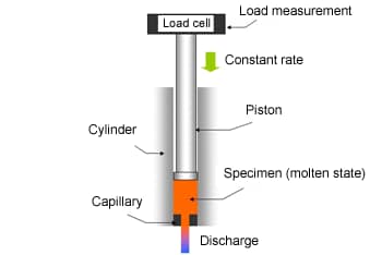 Fig. 6.10 Capillary rheometer
A capillary rheometer is used for that test method whereby the specimen melted in a cylinder is extruded through a capillary, in the same way as with the MFR. This method differs from the MFR method, however, in that the fluidity can be determined as melt viscosity (units: Pa・s), not as the resin weight per unit time. As shown in the schematic diagram (Fig. 6.10), a capillary rheometer detects the load when the molten resin is extruded with a piston at a constant rate, using a load cell, after which the melt viscosity is determined by applying Formulas 6.2 to 6.5. For PPS, which is a non-Newtonian fluid, the detected load (shear stress) varies with the piston rate (shear rate), so that the shear rate dependence of the melt viscosity can be determined by changing the piston rate at will. Note, however, that the shear rate determined by calculation is called the apparent shear rate (or shear stress), not the true shear rate (or shear stress) on the capillary wall. If the shear rate is used in CAE analysis, it is corrected to a true value, using Bagley correction, Rabinowitsch correction, and so on, to improve analysis accuracy. This technical document refers to uncorrected shear rate and shear stress, unless stated otherwise.
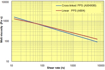 Fig. 6.11 Sear rate
dependence (320℃, L/D = 40/1)
Fig. 6.11 Sear rate
dependence (320℃, L/D = 40/1)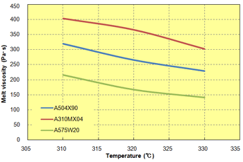 Fig. 6.12
Temperature dependence (L/D = 40/1, shear rate: 608/sec)
Fig. 6.12
Temperature dependence (L/D = 40/1, shear rate: 608/sec)
In general, the shear rate dependence of the melt viscosity is expressed as a double logarithmic chart to
indicate the properties over a wide range. PPS is classified as a pseudoplastic fluid because the melt
viscosity varies with the shear rate and, in particular, the melt viscosity decreases as the shear rate
increases.
Fig. 6.11 shows the melt viscosity of glass fiber reinforced PPS of "TORELINA™," relative to the
shear rate. The slope of the shear rate dependence depends a combination of factors, such as the polymer
structure and the additive type. For PPS, in particular, the slope of the shear rate dependence differs
depending on whether it is cross-linked PPS or linear PPS. For cross-linked PPS, the slope is large
because the sensitivity is high relative to the shear rate, whereas for a linear PPS, the slope tends to
be small.
The melt viscosity is temperature-dependent, and decreases as the temperature rises. (Fig. 6.12) In
injection molding, mold filling may be improved by increasing the injection speed. The reason for this is
believed to be that viscosity decreases occur with high shear rates (shear rate dependence) and, in
addition, the resin temperature rises due to shear heating (temperature dependence) also have an
influence. If the fluidity is to be judged using the melt viscosity properties, an appropriate shear rate
range must be confirmed according to the molding method and the shape. In injection molding, a rough guide
for fluidity is an area of about 100 to 1000 (/s).
The shear rate dependence of the melt viscosity of various grades of TORELINA™ is shown in Figs. 6.13 to 6.21. In general, the higher the reinforcement content, the lower the fluidity, but TORELINA™ A575W20 and A495MA2 both offer excellent fluidity.
[General reinforced grades]
1 A504X90 (standard) and A604
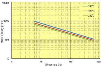 Fig. 6.13 Shear rate dependence (A504X90)
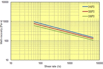 Fig. 6.14 Shear rate dependence (A604)
2 A310MX04 (standard) and A610MX03
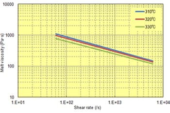 Fig. 6.15 Shear rate dependence (A310MX04)
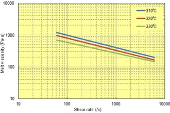 Fig. 6.16 Shear rate dependence (A610MX03)
[Elastomer improvement grades]
3 A575W20, A673M, and A495MA2
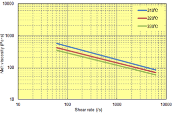 Fig. 6.17 Shear rate dependence (A575W20)
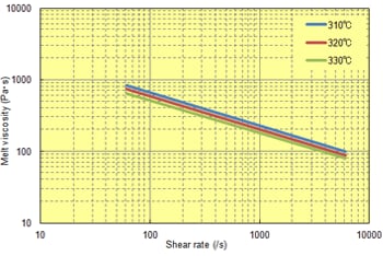 Fig. 6.18 Shear rate dependence (A673M)
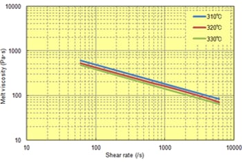 Fig. 6.19 Shear rate dependence (A495MA2)
[Unreinforced grades]
3 A900 and A670T05
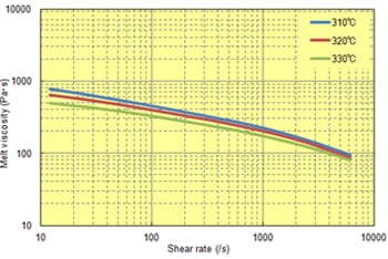 Fig. 6.20 Shear rate dependence (A900)
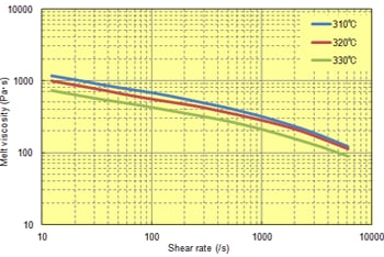 Fig. 6.21 Shear rate dependence (A670T05)
Ⅲ. Bar flow
The bar flow is used in a fluidity evaluation method using an actual injection molding
machine and a mold. The bar flow depends on the molding conditions and the shape, so that it can be used to
relatively judge the fluidity by specifying fixed conditions for the molding temperature, mold temperature,
injection pressure, injection speed, and test shape, among others. The bar flow is a fluidity index that
considers not only the melt viscosity but also other factors such as the solidification properties of the
material. As such this index is very practical.
The spiral flow bar flow (convoluted type) for a 1-mm thickness of TORELINA™ is given in Table. 6.5.
The bar flow differs depending on the reinforcement content and whether PPS is improved with
elastomers.TORELINA™"A575W20 offers excellent fluidity, however. In injection molding, a material with
a higher fluidity can satisfy a wider range of molding conditions, and can be used to form a wider variety
of shapes.
Table. 6.5 Spiral bar flow (1 mm t) of TORELINA™
| Item | Units | Glass fiber reinforced | Glass + filler reinforced | Elastomer improvement | Unreinforced | |||||
|---|---|---|---|---|---|---|---|---|---|---|
| A504X90 | A604 | A310MX04 | A610MX03 | A673M | A575W20 | A495MA2 | A900 | A670T05 | ||
| Bar flow | mm | 135 | 120 | 105 | 90 | 150 | 200 | 140 | 200 | 150 |
- ※ Molding conditions (settings): Molding temperature: 320℃, mold temperature: 130℃, injection pressure: 98 MPa, and injection speed: 100 mm/s