- HOME
- Technical Information
- TORELINA™ PPS Resin
- Various Properties
- Secondary Processing
- Physical Joining
Physical Joining
Ⅰ. Thermal Welding Methods
If multiple molded products are to be combined into a single part, thermal welding methods are generally used for thermoplastic resins. With the thermal welding method, the joint interface of molded products is melted, using the method shown in Fig. 10.1, and then cooled while the joint is held together under pressure, thus joining the molded products, as shown in Fig. 10.7. The strength of the weld portion results from the entanglement and crystallization caused by molecular diffusion at the joint interface. Basically, therefore, products of the same type of PPS resin can be combined, but it may also be possible to join products of dissimilar materials if their polymers have similar solubility parameter (SP) values. When PPS resin is used, and it is to be joined to another polymer (such as polyamide or polyester), special material designs, such as polymer alloys, are necessary. There are cases in which dissimilar materials are combined together through multi-layer extrusion, as in the case of films and tubes. For information about joining dissimilar polymers, contact us.
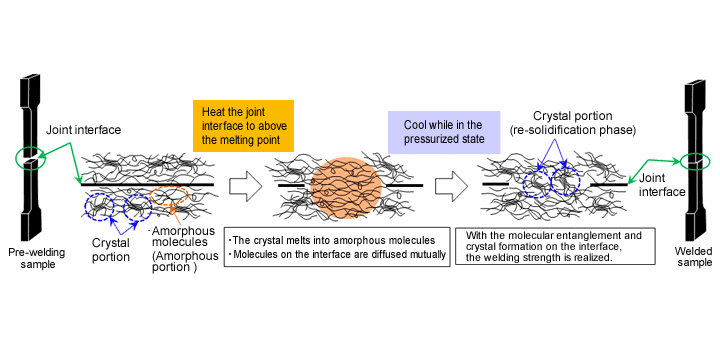
Fig. 10.7 Mechanism of thermal welding
Ⅱ. Comparison of the Features of Thermal Welding Methods
Features of the typical thermal welding methods that can be used to join TORELINA™ are listed in Table. 10.8. Different welding methods have different features, so must be selected appropriately by considering the size and shape of the product, the properties demanded of the product, and economies (such as the equipment price and the cycle).
Table. 10.8 Comparison of features of thermal welding methods
| Item | Representative thermal welding method | |||||
|---|---|---|---|---|---|---|
| Hot-plate welding | Ultrasonic welding | Vibration welding | Spin welding | Laser welding | DSI molding | |
| Compatible shapes (Limitations) |
Other than extreme 3-D shapes | Relatively small parts (Limited due to the molded product size) |
Other than extreme 3-D shapes (Limited due to the vibration direction) |
Cylindrical shapes only | Relatively thin wall parts (Limited due to laser beam transmission) |
Shapes that can be released from the mold |
| Compatible materials | Some thermoplastic resins not permitted | Thermoplastic resins in general | Thermoplastic resins in general | Thermoplastic resins in general | Some not permitted (Combination of transmitting material and absorber) |
Thermoplastic resins in general |
| Joint appearance | Some of the resin runs off. |
Some of the resin runs off. |
Some of the resin runs off. |
Some of the resin runs off. |
Good | Good |
| Welding cycle | Slow | Fast | Fast | Fast | Fast | Product extraction: 1 time/2 shots |
| Power consumption | Low | Low | Medium | Low | Low | High |
| Reproducibility | Medium | High | High | High | High | High |
| Influence on built-in parts | Heat | Vibration | Vibration | Rotation | None | - |
Ⅲ. Selecting the Grade of TORELINA™
If a thermal welding method is to be applied, regardless of the method to be selected, the properties necessary for enhancing the molecular entanglement effect used to obtain a high welding strength are common to all methods. When selecting materials, note the following points, in addition to the mechanical properties suited to the product properties.
◆Points related to the selection of PPS grades for thermal welding
- Linear PPS
- High molecular weight (low fluidity)
- Slow to solidify (low crystallization temperature, elastomer improvement, etc.)
- Low reinforcement material content
◆TORELINA™ grades recommended for thermal welding
Unreinforced PPS resin in general: A900 and A670 series
Linear PPS: A602 and A604 series
Elastomer improvement PPS: A673M
- ※Cross-linked PPS and high-filler grades can also be subject to thermal welding, but they tend to exhibit a lower welding strength and optimum welding condition width (process window) than the recommended grades.
Ⅳ. Hot-Plate Welding
As shown in Fig. 10.8, joining with hot-plate welding is a method whereby the portions of molded products to be welded are melted with a hot-plate, and then the melted portions are matched together, and held together under pressure until they have cooled and hardened.
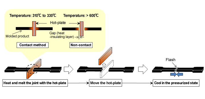
Fig. 10.8 Processes of hot-plate welding method
The melting of molded products with a hot-plate can be largely divided into two types, namely, the contact method, whereby the molded products are melted by bringing a hot-plate directly into contact with them, and the non-contact method, whereby they are melted indirectly by radiated heat from a hot-plate.
With the contact method, because the conductivity of the heat from the hot-plate to the molded products is high, the temperature of the hot-plate need only be equal to the melting point of the resin, plus about 20℃ to 50℃. For TORELINA™, welding is possible with a hot-plate set to 300℃ to 330℃. Relative to the non-contact method, a relatively wide process window can be secured, but because the molded products are brought into direct contact with the hot-plate, hot-plate state management (including mold release treatment for the resin) is important to prevent cobwebbing.
With the non-contact method, air layers, which have a high heat insulating effect, exist between the hot-plate and the molded products, so the hot-plate must be set to a temperature higher than that for the contact method. Usually, the hot-plate temperature must be at least 600℃, although this depends on the dimension of the gap between the hot-plate and the molded products. If the gap between the hot-plate and the molded products is too small, or if the hot-plate temperature is increased more than necessary, the thermal history of the surfaces of the molded products will be exceedingly high, causing gas generation due to resin decomposition, resulting in welding failure. It is, therefore, important to understand the relationship between the gap distance and the hot-plate temperature. With the non-contact method, on the other hand, the process window is narrow, but no resin will adhere to the hot-plate. Thus, it is easy to manage the hot-plate. This method is better suited for continuous production.
The main conditions factors influencing welding are the hot-plate temperature, heating time, and welding allowance. They also include the melting allowance in the case of the contact method, and the distances (mm) of the gaps between the test pieces and the hot-plate in the case of the non-contact method. The welding allowance is the stroke (mm) or pressure (MPa) with which the molded products are pressed together after being melted, while the melting allowance is the stroke (mm) or pressure (MPa) with which the molded products are pressed against the hot-plate during heating. If the melting allowance and the welding allowance are too small, there will be insufficient melting and insufficient welding. If these parameters are too large, the amount of resin discharged as flash will increase, and insufficient welding will result.
◆Test example - Hot-plate weldability of TORELINA™ -
The hot-plate weldability of TORELINA™ is given in Table. 10.9. Unreinforced PPS resin exhibits a different elongation depending on the hot-plate temperature, but it is possible to achieve a welding strength that is almost the same as the tensile strength of the base material. In contrast, the elastomer improvement type, A575W20, produces a welding strength that is less than 30% of the strength of the base material. On welded portions, stress concentration is likely to occur because the orientation of the reinforcement is disturbed and the crystal state differs from that of the surroundings, so a high level of strength comparable to that of the base material cannot be obtained. For A310MX04, which has a high reinforcement content, even though the apparent joint area is the same, the reinforcement impedes the diffusion of the PPS molecules, so the true joint area influencing welding is smaller than that of other materials, and thus the welding strength is lower.
Table. 10.9 Hot-plate weldability of TORELINA™ (contact method)
| TORELINA™ Grade |
Hot-plate welding condition | Hot-plate welding property | ||||||
|---|---|---|---|---|---|---|---|---|
| Hot-plate temperature (℃) |
Heating time (sec) |
Melting allowance (mm) |
Welding allowance (mm) |
Cooling time (sec) |
Tensile strength (MPa) |
Tensile fracture elongation (%) |
Fracture mode | |
| A670X01 (Unreinforced PPS) |
300 | 60 | 0.8 | 0.9 | 30 | 42 | 14 | Base material surface layer fracture |
| 310 | 60 | 0.8 | 0.9 | 30 | 43 | 35 | Base material fracture | |
| A575W20 | 320 | 30 | 0.9 | 1.2 | 30 | 40 | 1.0 | Base material surface layer fracture |
| A310MX04 | 320 | 30 | 0.9 | 1.2 | 30 | 16 | 0.4 | Interface fracture |
Shape: ASTM No. 1, cut in half, the strokes as the melting and welding allowances being the travel distances on both sides
Ⅴ. Ultrasonic Welding
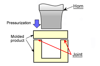 Fig. 10.9 Ultrasonic welding method
Ultrasonic welding is a method whereby the joint surfaces are melted by friction heating, using ultrasonic waves (20 to 40 kHz), after which the surfaces are joined together. In ultrasonic welding, a resonator (called a horn) is brought into contact with part of a molded product, as shown in Fig. 10.9, and ultrasonic vibration is applied to the molded product. The vibration energy caused by the ultrasonic waves is converted into thermal energy due to repeated impacts with the other molded product at the joint interface (friction heating), thus melting the PPS resin. A method involving joining at a position some distance from the horn, like that described here, is called transfer joining. It is important to suppress the attenuation of the ultrasonic waves, and to propagate the waves through a molded product efficiently, so that they are concentrated on the joint. In general, the larger a molded product, the greater the distance between the horn and the joint surface. Any attenuation of the ultrasonic waves will reduce the weldability. Thus, this welding method is suitable for small molded products.
If ultrasonic welding is to be performed, a high welding strength can be achieved and the welding time can be reduced by optimizing the horn shape, the position at which to bring the horn into contact with the product, the joint design, and so on. Regarding the joint design, which is particularly important, flat joint surfaces (butt joints) will cause the ultrasonic waves to diffuse, resulting in variations in the welding. Therefore, the joint surfaces should be provided with projecting energy directors (called EDs in the remainder of this document), as shown in Fig. 10.10. It is important to make sure that the sizes of the EDs match that of the welding area. If the EDs are too small, the welding area will be small, resulting in insufficient welding strength. If the area is too large, on the other hand, flash will result.
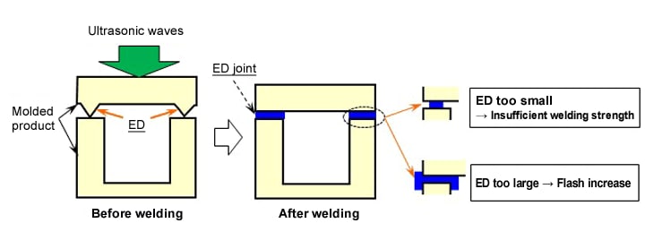
Fig. 10.10 Energy directors (butt joint)
For TORELINA™, which is highly crystalline, there will be cases, with larger products, in which sufficient welding strength cannot be obtained with EDs. In such cases, the welding strength can be increased by adopting fitting shapes such as share joints, scarf joints, and beat joints, as shown in Fig. 10.11. For cylindrical shapes, in particular, share joints are advantageous for ultrasonic welding.
◆Test example - Ultrasonic hot-plate weldability of TORELINA™ -
The results of testing the ultrasonic weldability of TORELINA™, using the hat-shaped cylindrical shape (share join) shown in Fig. 10.12, are shown in Figs. 10.13 and 10.14. The upper molded product was fixed, the indenter was inserted through the opening at a rate of 5 mm/min to apply load to the lower molded product. The welding load shown is that load at which a fracture of the welded portion occurred. The ultrasonic weldability varies with the welding time and the pressure applied, and it can be seen that the welding time has greater influence on the welding strength. In addition, if the welding time is increased when a high pressure is applied, the melting allowance will be discharged as flash and the influence of any residual strain will increase, possibly causing the welding strength to decrease. There is a need, therefore, to set conditions within appropriate ranges. Also, the following tendency is observed: The linear polymer type, A604, is superior in terms of its ultrasonic weldability to cross-linked polymer type, A504X90.
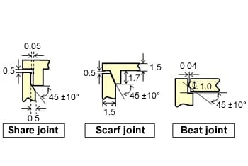 Fig. 10.11 Examples of fitting structures for ultrasonic welding
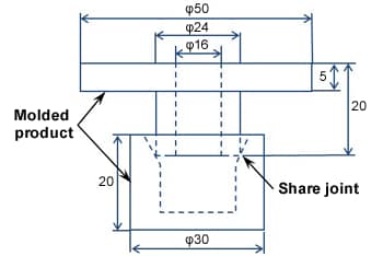 Fig. 10.12 Ultrasonic weldability evaluation shape (Toray method)
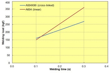 Fig. 10.13 Ultrasonic weldability (welding time dependence) of TORELINA™
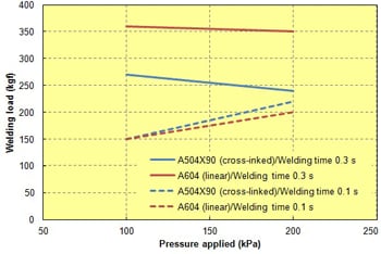 Fig. 10.14 Ultrasonic weldability (pressure dependence ) of TORELINA™
- ※Oscillating frequency: 20 Hz, pressure dependence and pressure applied = 100 kPa
Ⅵ. Vibration Welding
Vibration welding is a method that involves fixing one molded product, while another molded product is vibrated laterally with pressure applied, so that the friction melts the products where they meet, such that they can be joined together. As shown in Fig. 10.15, a vibration welding machine generates lateral vibrations by using a mechanism in which an electromagnetic coil works against a spring, causing the joint surfaces to rub together repeatedly at a constant amplitude (1 to 1.8 mm at a vibration frequency of 240 Hz). As a result of the heating caused by the friction between the surfaces, a melting allowance is gradually formed on the surfaces of the molded product, part of which is discharged as flash due to the pressure applied. When the preset welding depth (about 1 to 2 mm) is reached, the welding machine moves to the cooling process. Vibration welding takes about 3 to 10 seconds, so the welding cycle is longer than that of ultrasonic welding. This technique is used if the product is too large for ultrasonic welding. For example, vibration welding is adopted for hollow molded objects that are both large and complex in shape, such as car intake manifolds.
One point that must be considered regarding vibration welding is that it is limited to lateral vibration, so if the joint surface has a complex three-dimensional shape, joining may fail unless the part is divided into several sections. It is thus necessary to design a joint by considering the vibration direction. For the general joint shape shown in Fig. 10.15, the vibration energy is dispersed, leading to variations in the welding. In such a case, it is effective to provide a welding rib to concentrate the vibration energy on the joint, as well as a flash pool to eliminate the need for deflashing.
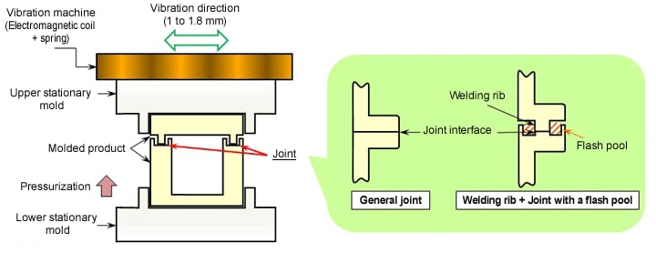
Fig. 10.15 Configuration of a vibration welding machine and example joint shape
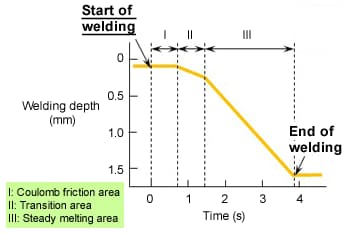 Fig. 10.16 Three phases of vibration welding
During vibration welding, the state of a joint can be divided into one of three phases, as shown by the illustration of the relationship between time and welding depth in Fig. 10.16. These are the coulomb friction area (Ⅰ), from immediately after the start of welding to a point near that where the melting point is reached, the transition area (Ⅱ),where the state changes from solid to molten, and the steady melting area (Ⅲ), where the melting point has been reached sufficiently and melting progresses steadily. The welding time is the total of these three phases. In addition to the material composition, the time is affected by three main condition factors, namely, the amplitude, the pressure applied, and the welding depth. The pressure applied is, in particular, an important factor influencing the friction coefficient and the slope of the steady melting area.
For a joint for which a welding rib is provided, as shown in Fig. 10.17, pay careful attention to the effective welding range ("W" in the figure), which contributes the welding strength. For any given welding depth, the melting state of the corners of the welding rib when a low pressure is applied differs from that when a high pressure is applied. This leads to variations in the welding area, with the following tendency being apparent: The lower the pressure applied, the higher the welding strength, although the welding time is longer.
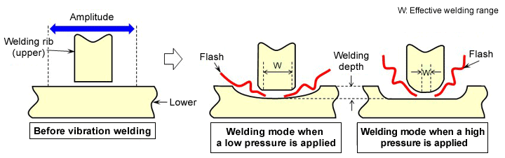
Fig. 10.17 Effective welding range of a welding rib
◆Test example 1 - Dependence of molded products provided with welding ribs on pressure applied -
A hollow molded product is manufactured by means of vibration welding, using the pipe shape (provided with a welding rib) shown in Fig. 10.18. The pressure resistance of the product is determined through the application of a water pressure test. Fig. 10.19 shows the relationship between the pressure applied and the welding time. As the graph shows, the welding time becomes shorter as more pressure is applied. The reason for this is regarded as being the fact that, the higher the pressure applied, the higher the friction coefficient of the joint surface, thus the shorter the coulomb friction area and, in addition, the greater the slope of the steady melting area (Fig. 10.16). As shown in Fig. 10.20, TORELINA™ A604 (reinforced with 40% GF) tends to exhibit a falling pressure resistance as the pressure applied is increased. The reason for this is assumed to be the fact that the higher the pressure applied, the smaller the effective welding range and, in addition, the greater the residual strain (Fig. 10.17). On the other hand, TORELINA™ A673M has a low reinforcement content, and the elastomer reduces the residual stress and stress concentration, making it superior to A604 in terms of weldability.
Compared to nylon resin, used for car intake manifolds and so on (30% N6GF), PPS resin tends to exhibit a slightly lower weldability due to the difference in its crystallinity and other factors.
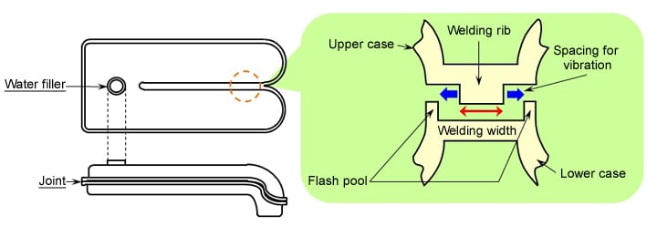
Fig. 10.18 Molded product shape and weld shape for a pressure test
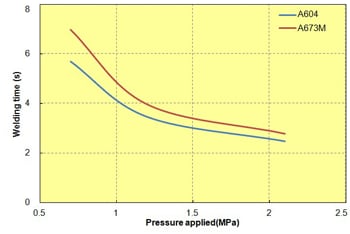 Fig. 10.19 Pressure applied in relation to welding time
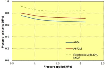 Fig. 10.20 Pressure applied in relation to pressure resistance
- ※Welding depth: 1.5 mm, amplitude: 1.5 mm, molding temperature: 320℃, mold temperature: 80℃ (low-temperature mold molding), no annealing
Pressure resistance: Value on pressure gage attached to the hydraulic tester
◆Test example 2 - Vibration weldability of TORELINA™ -
Using the test piece (no welding ribs) shown in Fig. 10.21, vibration welding was performed. The test piece was cut into rectangles (t: 3 mm) (the end faces were milled). Fig. 10.22 shows the vibration weldability of GF-reinforced grades. A602LX01 (reinforced with 20% GF), which has a low GF content and is slow to solidify, tends to have a high vibration weldability. In comparison with the cross-linked polymer type A504X90, linear polymer type A604 is superior in terms of ultrasonic weldability. The vibration weldability of the elastomer improvement and unreinforced grades is shown in Fig. 10.23. It can be seen that A575W20, with a high reinforcement content, exhibits a low welding strength, whereas the unreinforced PPS has a high welding strength. A670T05, improved with an elastomer, in particular, has a welding strength comparable to that of the base material, and is excellent in terms of its vibration weldability.
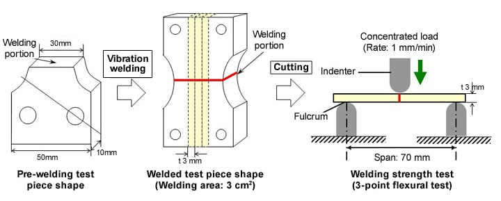
Fig. 10.21 Preparation of vibration weldability evaluation test pieces; and test conditions
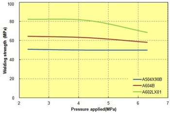 Fig. 10.22 Vibration weldability of GF-reinforced grades
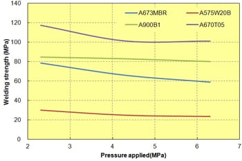 Fig. 10.23 Vibration weldability of elastomer improvement and unreinforced grades
- ※Welding depth: 1.5 mm, amplitude: 1.5 mm, molding temperature: 320℃, mold temperature: 80℃, annealing: 130℃ × 1 hr
Ⅶ. Laser Welding
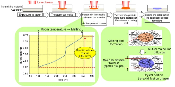
Laser welding is basically used for lap joining. As shown in Fig. 10.24, the energy of a laser beam is converted to thermal energy on the laser absorber surface, causing the surface to melt, after which heat transfer causes the other molded product to melt, such that they can be joined together. Laser welding is often used for metals. For the lap joining of metals, everything from the surface to the joint is melted. For thermoplastic resins, the laser beam is converted into thermal energy at the joint through a transmitting material, as described earlier, which means that only the joint melts. As a result, the strain caused by the heat is low, and a high welding strength can be obtained. With thermal welding methods such as hot-plate welding, part of the melting allowance is discharged as flash. A great feature of laser welding is that it can perform welding without discharging any of the melting allowance, enabling flash-less welding. There are limits on the combinations of transmitting material and absorber. In general, use a combination of a transmitting material in a natural color and an absorber colored black through the addition of carbon black, etc.
In laser welding, the application of pressure to the joint surface does not consist of pressing the melting allowances with an external force, as in the case of hot-plate welding, but it is basically performed by exploiting the increase in pressure that occurs at the joint interface due to the volume expansion during melting (specific volume changes). If the gap between the molded products is large, it is not possible to attain a sufficiently high pressure due to there being specific volume changes. As a result, there will be insufficient heat transfer to melt the transmitting material. Thus, the pressure to be set for laser welding is intended for correction and retention.
Fig,10.24 Laser welding method and mechanism
As described earlier, thermoplastic resin laser welding involves a transmitting material and an absorber. The laser transparency of the transmitting material is particularly important. There are a variety of laser types, such as semiconductor lasers (wavelength: 635 to 940 nm), Nd: YAG lasers (wavelength: 1060 nm), and CO2 lasers (wavelength: 9600, 10,600 nm). The transmitting material must have a transmittance of 15% or greater in the wavelength domain being used, or 20% or greater if the process window is to be widened (to enhance production stability). In general, a material made by blending a highly crystalline polymer with reinforcement, such as PPS resin, is not suitable for laser welding, because the laser beam is attenuated by the molded product due to reflection and diffusion by the crystal structure and the reinforcement (GF and/or mineral filler), so that the beam is converted into energy in the transmitting material causing it, rather than the joint surface, to melt.
TORELINA™ A602LX01 is a Laser welding grade that suppresses the attenuation of laser beams and offers a high laser transmittance by optimizing the reinforcement and the crystallinity of the PPS polymer. Its properties are listed in Table. 10.10.
Table. 10.10 Properties of TORELINA™ A602LX01 (Laser welding grade)
| Item | Units | Laser welding grade | General grade | |
|---|---|---|---|---|
| A602LX01 | A604 | |||
| Density | kg/m3 | 1480 | 1660 | |
| Tensile strength | MPa | 140 | 190 | |
| Tensile elongation | % | 2.0 | 2 | |
| Flexural strength | MPa | 200 | 290 | |
| Flexural modulus | GPa | 8.0 | 15.0 | |
| Charpy impact strength | kJ/m2 | 9 | 11 | |
| Laser beam transmittance (Wavelength: 940 nm) |
t1mm | % | 35 | 17 |
| t2mm | % | 23 | 6 | |
| t3mm | % | 9 | 2 | |
| Laser welding strength | 2mmt | MPa | 42 | Welding not possible |
- ※Laser welding conditions: 30 W output, scanning rate: 5 mm/s, lap joining
◆Laser weldability evaluation method
Laser weldability is determined from the tensile shear strength of a test piece prepared under the conditions described below.
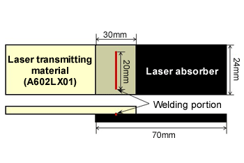 Fig. 10.25 Laser welding shape
(Conditions for preparing welding test pieces)
Welding machine: Rated output of 35 W, semiconductor laser
Wavelength: 940 nm
Focus diameter: 0.6 mm (just focus)
Joining format: Lap method (Fig. 10.25)
Welding length: 20 mm
Tension rate: 1 mm/min
Laser transmitting material: TORELINA™ A602LX01 (t: 1 mm)
Laser transmittance: 35% (wavelength: 940 nm)
◆Test example 1 - Dependence of laser welding conditions -
The relationship between the laser welding conditions and the welding strength is given in Table. 10.11 and Figs. 10.26 and 27. Judging from the fact that, if the absorber surface heat quantity is 0.14 J/mm or less, melting does not occur. If it is 0.88 J/mm or greater, foaming is confirmed, and it is regarded that the resin temperature has reached 400℃ or greater due to there being excess input energy, causing foaming with cracked gas.
The tensile shear load, shown in Fig. 10.26, increases with the absorber surface heat quantity but, at the same time, the welding area also increases. Thus, if the tensile shear load is converted into a tensile shear stress (Fig. 9.28) by dividing it by the actual welding area, it can be seen that the welding strength is saturated with a surface heat quantity of about 0.25 to 0.7 J/mm, and if the heat quantity increases above 0.7 J/mm, the welding strength decreases due to foaming. Thus, it is assumed that, if laser welding is performed by using TORELINA™ A602LX01, a stable high welding strength can be attained by setting the conditions in such a way as to achieve a heat quantity of about 0.25 to 0.7 J/mm.
Table. 10.11 Relationship between TORELINA™ A602LX01 laser welding conditions and welding strength
| Item | Units | Results | |||||||
|---|---|---|---|---|---|---|---|---|---|
| Output | W | 20 | |||||||
| Scanning rate | mm/s | 50 | 30 | 25 | 20 | 15 | 10 | 8 | 5 |
| Absorbing-side surface heat amount※1 | J/mm | 0.14 | 0.23 | 0.28 | 0.35 | 0.47 | 0.70 | 0.88 | 1.40 |
| Welding state (cross section)※2 | - | Problem detected (Not welded) |
No problem detected | No problem detected | No problem detected | No problem detected | No problem detected | Problem detected (Foaming) |
Problem detected (Foaming) |
| Tensile shear load | N | 0 | 583 | 770 | 980 | 1125 | 1270 | - | 1000 |
| Tensile shear stress | MPa | 0 | 38 | 38 | 38 | 38 | 36 | - | 20 |
| Welding area※3 | mm2 | 0 | 15.3 | 20.3 | 25.8 | 29.6 | 35.3 | - | 50 |
- ※1 Absorber surface heat quantity (J/mm) = {Output (W)} / {Scanning rate (mm/s)} x {Transmitting material-side specimen transmittance (%)}
- ※2 Welding state: Confirmed by observing a cross section with a polarizing microscope.
- ※3 Welding area: The welded area was determined by observing the fracture surface after the tensile test.
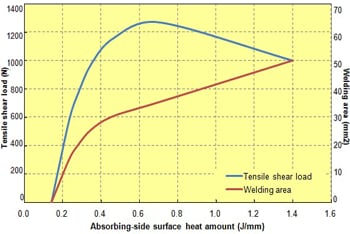 Fig. 10.26 Relationship between laser welding conditions and tensile shear load
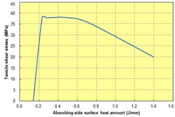 Fig. 10.27 Relationship between laser welding conditions and tensile shear stress
◆Test example 2 - Influence of gap during laser welding -
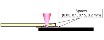 Fig. 10.28 Gap (dummy) forming method
For laser welding, if the joint surface has a gap, which influences the welding strength. The main causes of gaps include warpage and shrinkage of the molded product. A spacer was inserted into the overlap between the transmitting material and the absorber to create a dummy gap, as shown in Fig. 10.28, and laser welding was executed. The results are shown in Figs. 10.29 and 10.30. In laser welding, the gap dependence is dependent on the surface heat quantity. This is considered because the pressure applied decreases due to specific volume changes, so that a reduction in welding area and the degree of mutual molecular diffusion become low. Thus, for laser welding, it is necessary to eliminate gaps whenever possible. Pay careful attention to gaps of 0.05 mm or more because they will lead to a drop in the reliability of the weld.
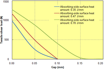 Fig. 10.29 Gap dependence of laser welding conditions (shear load)
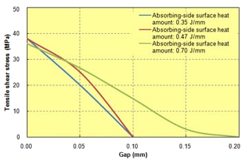 Fig. 10.30 Gap dependence of laser welding (shear stress)
White paper
Waterproof x Vibration-less x Short tact time!!What are PBT and PPS resins, suitable for laser welding methods?

Electronic Device Components are increasing in functionality, which creates new challenges for joining the thermoplastic resin components while maintaining high quality and high efficiency. This brochure provides material solutions using PBT and PPS materials, which produce high laser weld strength to deliver stronger, higher quality components while minimizing the impact of heat and stress during the welding process.
Technology advancements in high-performance laser welding resin thermoplasticsUsage and characteristics of laser weldable PBT and PPS

Laser welding of thermoplastics is becoming preferred methods to enhance quality of components manufacturing. Here, we will explain the advancements in PBT and PPS compounds are used for laser welding method including the unique features.
Ⅷ. Injection Welding (DSI Molding)
Injection welding is a method whereby a primary molded product is inserted into a mold, using an injection molding machine, after which secondary material is injection-molded, causing it to become welded to the primary molded product. die slide injection (DSI) molding was developed by The Japan Steel Works, Ltd., using a 2-cylinder injection molding machine. It is a type of 2-color molder that performs primary molding and secondary molding continuously, by using the slide mechanism of the mold. It is capable of producing hollow objects by injection molding.
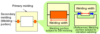 Fig. 10.31 Example of joining with DSI molding (in comparison with vibration welding)
In welding based on DSI molding, a secondary material is injection-molded onto the joint interface between primary molded products, and the primary material joint interface is melted and joined by the heat from the secondary material, as shown in the example of joining a box-like hollow object in Fig. 10.31. If the state of the joint surface is compared with that attained with vibration welding shown in Section 10.3.6, it can be seen that vibration welding requires a gap for the amplitude and a flash pool, whereas with DSI molding, welding is possible over the entire surface that is in contact with the primary material, so that a large welding area can be secured and, therefore, a high welding strength can be obtained. In comparison with a case in which primary molded products are taken out first and then subjected to insert-welding, DSI molding ensures a high welding strength because the temperature of the primary molded products is high and subsequent crystallization does not progress.
A cycle of injection welding using DSI molding is shown in Fig. 10.32. By moving the slide core on the moving side using a hydraulic unit, a hollow part can be molded continuously while switching between the primary and secondary materials. The moldability required of the primary material is the same as that for normal injection molding. For the secondary material, the fluidity and the solidification properties are important because the secondary material is required to flow up to the flow end while retaining the heat quantity for melting the primary material. Usually, the primary and secondary materials are a combination of the same type, from the viewpoints of weldability and economics, but because a DSI molding machine contains two cylinders, the materials need not necessarily be of the same type. There are cases in which, if the fluidity of the primary material is low or the solidification rate is high, a higher welding strength can be obtained by changing the secondary material.
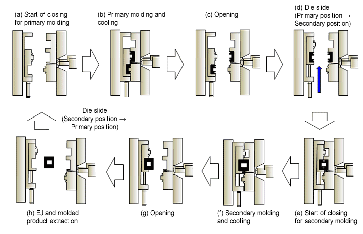
Fig. 10.32 Injection welding cycle with a DSI molding machine
◆Test example - Pressure resistance with DSI molding -
A hollow molded product was manufactured with DSI molding, using the pipe shape shown in Fig. 10.33. The pressure resistance was determined by a water pressure test. Fig. 10.34 shows the DSI weldability of TORELINA™. Linear polymer type A604 is superior to cross-linked polymer type A504X90 in terms of weldability. A310MX04, which has a high reinforcement content, has a low fluidity, so it cannot be welded with short shots during secondary material molding. A575W20, which is excellent in terms of fluidity, can be welded with short shots. Note, however, that the pressure resistance is slightly lower due to the influence of the reinforcement content. Elastomer improvement type A673M has a high pressure resistance, and offers a pressure resistance about three times greater than that of the same shape manufactured with vibration welding.
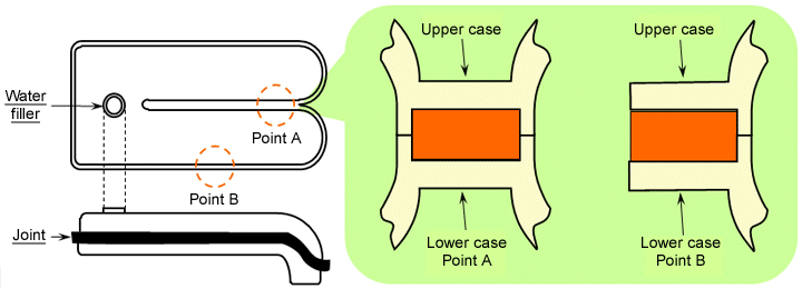
Fig. 10.33 Molded product shape and weld shape for a pressure test
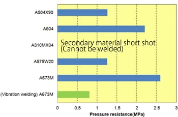 Fig. 10.34 DSI weldability of TORELINA™
- ◆DSI molding conditions
Molding machine: J220E2-M2 made by The
Japan Steel Works, Ltd.
Molding temperature:
Primary material (nozzle side)
320-320-310-300 (℃)
Secondary material (nozzle side)
320-320-310-300 (℃)
Mold temperature: 140℃