- HOME
- Technical Information
- TORELINA™ PPS Resin
- Injection Molding
- Mold
- Supplementary Notes on Mold Design
Supplementary Notes on Mold Design
Ⅰ. Corner Radiuses
At those portions where the resin flow path direction or the wall thickness changes abruptly, corner radiuses must be provided to reduce the stress concentration coefficient and to make the resin flow smooth.
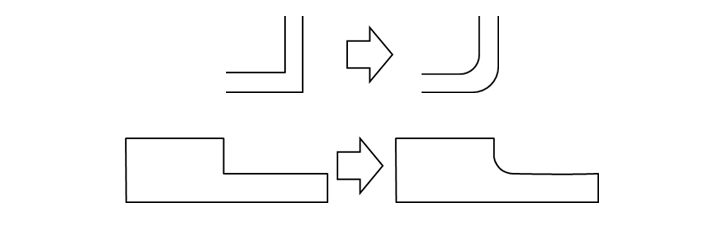
Fig. 4.1 Corner radius examples
The relationship between the corner radiuses and the stress concentration coefficient is shown in Fig. 4.2. TORELINA™ is a material with a relatively low notch sensitivity, but many cases of damage that may occur to products can be prevented by providing sufficiently large corner radiuses. It is recommended that corner radiuses of at least 0.5 be provided.
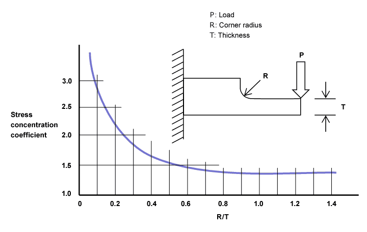
Fig. 4.2 Corner radius in relation to the stress concentration coefficient
Molten resin flows into the mold while expelling the air inside. If there are any sharp corners, it may not be possible to discharge the air at that portion, causing the air to get caught in the resin and resulting in molded product defects such as voids.
Ⅱ. Sprue
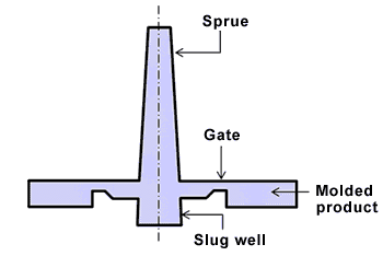 Fig. 4.3 Sprue shape example
For the sprue shown in Fig. 4.3, the sprue bush side of the mold must be designed with a radius slightly larger than that of the nozzle tip, so that resin will not leak from the nozzle tip. The inlet of the sprue must be designed with a diameter equal to the diameter of the nozzle of the molding machine plus about 0.5 to 1.0 mm. If the diameter is too large relative to the nozzle diameter, this may result in problems due to the air that may get caught in from this portion. Preferably, the draft taper of the sprue should be at least 4°. Provide a slug well that also provides gas venting. To avoid remnant sprue, provide a sprue lock pin (Z pin) by using a slug well, polish the inside sufficiently, and finish it in the longitudinal direction.
Ⅲ. Runner
Runners may have circular, semicircular, trapezoidal, or other cross-sectional shapes. Circular shapes are the most common because they present the lowest flow resistance. It is necessary to design a runner with a diameter that is sufficiently greater than the wall thickness. The reason for this is that if the solidification time of the runner is shorter than that of the molded product, a sufficient holding pressure will not act on the molded product, leading to sink marks, voids, poorer dimensional accuracy, and so on. Once the size of the molded product, the number of gates, the number of cavities, and so on are decided, the runner length will be close to being decided. It can be said that it is preferable for the runner to be as short as possible to minimize any pressure reduction in the runner.
Assuming the runner diameter to be D(radius:r) and the runner length is L, they can be determined using the approximation formulas, Formulas 4.1 to 4.6.
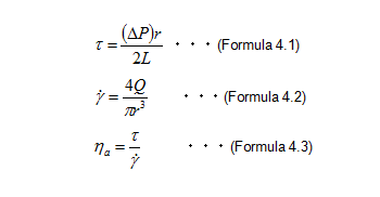
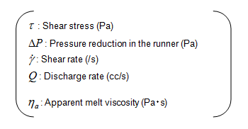
An appropriate shear rate when TORELINA™ flows through the runner ϒ is about 1000/s. The melt viscosity of A504X90 at a resin temperature of 330℃ η is 200 Pa・s. (See Fig. 4.4.)
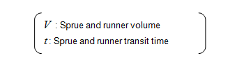
As described earlier, it is not possible to obtain a molded product with excellent quality unless the substantive filling time is 1 s or less. The following relationship holds true between the sprue and runner volume V and the transit time t.
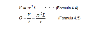
Assuming that ϒ=1000/s, plug Formula 4.2 into Formula 4.5, simplify the formula, and get
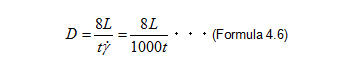
The relationship between the runner length and runner diameter, as determined from Formula 4.6, is shown in Fig. 4.5.
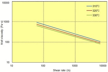 Fig. 4.4 Shear rate dependence of melt viscosity (A504X90)
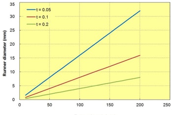 Fig. 4.5 Runner length in relation to the runner diameter
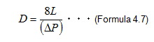
For an ordinary molded product with a sprue to runner ratio of about 15%, design the runner with a diameter such that the runner transit time is about 0.1 to 0.2 s. For a multi-cavity molded product, the gate balance will be lost if the portion close to the sprue and the farthest portion differ greatly in terms of pressure reduction. The balance must be adjusted by varying the gate diameter or the land length for each gate, but such adjustment becomes harder as the number of cavities increases. Therefore, any pressure reduction in the runner should be minimized. Assuming that ϒ is 1000/s and η is 200 Pa・s for A504X90, the shear stress τ generated is τ = 0.2 MPa from Formula 4.3. Plug this shear stress into Formula 4.1 and simplify and we will obtain Formula 4.7. (See Fig. 4.6.)
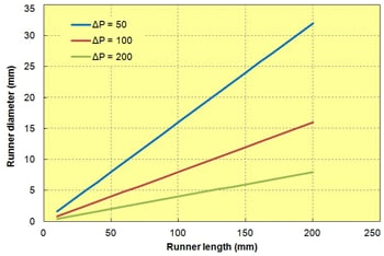 Fig. 4.6 Runner length in relation to the runner
For the same runner length, the larger the runner diameter, the smaller the pressure reduction. It is considered that, as a rough guide, the pressure reduction in the runner should not exceed 10% of the injection pressure. High-filler grades such as A310MX04 have a larger thermal diffusion than A504X90 (in other words, they are easier to cool), so the runner diameter should be 10% to 20% larger than that of A504X90. At the runner end, provide a slug well as shown in Fig. 4.7, to make sure that no gas is introduced into the molded product.
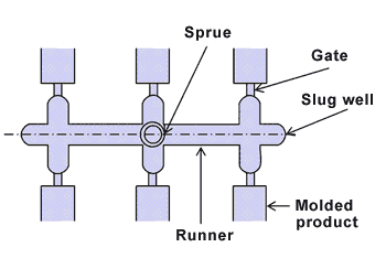
Fig. 4.7 Slug well shape example
A hot runner can be used to make a mold runner-less depending on the molding cycle and the pin gate combination, so it is more advantageous than a cold runner in terms of material yield, but is generally inferior to a cold runner in terms of dimensional accuracy. Decide whether to adopt a hot runner by considering the dimensional tolerances required of the molded product. Use a hot runner structured in such a way that the residing resin in the hot tip can be removed easily.